Visible to Intel only — GUID: exx1603918950344
Ixiasoft
1. F-Tile Overview
2. F-Tile Architecture
3. Implementing the F-Tile PMA/FEC Direct PHY Intel® FPGA IP
4. Implementing the F-Tile Reference and System PLL Clocks Intel® FPGA IP
5. F-Tile PMA/FEC Direct PHY Design Implementation
6. Supported Tools
7. Debugging F-Tile Transceiver Links
8. F-Tile Architecture and PMA and FEC Direct PHY IP User Guide Archives
9. Document Revision History for the F-Tile Architecture and PMA and FEC Direct PHY IP User Guide
A. Appendix
2.1.1. FHT and FGT PMAs
2.1.2. 400G Hard IP and 200G Hard IP
2.1.3. PMA Data Rates
2.1.4. FEC Architecture
2.1.5. PCIe* Hard IP
2.1.6. Bonding Architecture
2.1.7. Deskew Logic
2.1.8. Embedded Multi-die Interconnect Bridge (EMIB)
2.1.9. IEEE 1588 Precision Time Protocol for Ethernet
2.1.10. Clock Networks
2.1.11. Reconfiguration Interfaces
2.2.1. PMA-to-Fracture Mapping
2.2.2. Determining Which PMA to Map to Which Fracture
2.2.3. Hard IP Placement Rules
2.2.4. IEEE 1588 Precision Time Protocol Placement Rules
2.2.5. Topologies
2.2.6. FEC Placement Rules
2.2.7. Clock Rules and Restrictions
2.2.8. Bonding Placement Rules
2.2.9. Preserving Unused PMA Lanes
2.2.2.1. Implementing One 200GbE-4 Interface with 400G Hard IP and FHT
2.2.2.2. Implementing One 200GbE-2 Interface with 400G Hard IP and FHT
2.2.2.3. Implementing One 100GbE-1 Interface with 400G Hard IP and FHT
2.2.2.4. Implementing One 100GbE-4 Interface with 400G Hard IP and FGT
2.2.2.5. Implementing One 10GbE-1 Interface with 200G Hard IP and FGT
2.2.2.6. Implementing Three 25GbE-1 Interfaces with 400G Hard IP and FHT
2.2.2.7. Implementing One 50GbE-1 and Two 25GbE-1 Interfaces with 400G Hard IP and FHT
2.2.2.8. Implementing One 100GbE-1 and Two 25GbE-1 Interfaces with 400G Hard IP and FHT
2.2.2.9. Implementing Two 100GbE-1 and One 25GbE-1 Interfaces with 400G Hard IP and FHT
2.2.2.10. Implementing 100GbE-1, 100GbE-2, and 50GbE-1 Interfaces with 400G Hard IP and FHT
3.1. F-Tile PMA/FEC Direct PHY Intel® FPGA IP Overview
3.2. Designing with F-Tile PMA/FEC Direct PHY Intel® FPGA IP
3.3. Configuring the IP
3.4. Signal and Port Reference
3.5. Bit Mapping for PMA and FEC Mode PHY TX and RX Datapath
3.6. Clocking
3.7. Custom Cadence Generation Ports and Logic
3.8. Asserting Reset
3.9. Bonding Implementation
3.10. Independent Port Configurations
3.11. Configuration Registers
3.12. Configurable Quartus® Prime Software Settings
3.13. Configuring the F-Tile PMA/FEC Direct PHY Intel® FPGA IP for Hardware Testing
3.14. Hardware Configuration Using the Avalon® Memory-Mapped Interface
3.3.1. General and Common Datapath Options
3.3.2. TX Datapath Options
3.3.3. RX Datapath Options
3.3.4. RS-FEC (Reed Solomon Forward Error Correction) Options
3.3.5. Avalon® Memory Mapped Interface Options
3.3.6. Register Map IP-XACT Support
3.3.7. Example Design Generation
3.3.8. Analog Parameter Options
3.4.1. TX and RX Parallel and Serial Interface Signals
3.4.2. TX and RX Reference Clock and Clock Output Interface Signals
3.4.3. Reset Signals
3.4.4. RS-FEC Signals
3.4.5. Custom Cadence Control and Status Signals
3.4.6. TX PMA Control Signals
3.4.7. RX PMA Status Signals
3.4.8. TX and RX PMA and Core Interface FIFO Signals
3.4.9. PMA Avalon® Memory Mapped Interface Signals
3.4.10. Datapath Avalon® Memory Mapped Interface Signals
3.5.1. Parallel Data Mapping Information
3.5.2. TX and RX Parallel Data Mapping Information for Different Configurations
3.5.3. Example of TX Parallel Data for PMA Width = 8, 10, 16, 20, 32 (X=1)
3.5.4. Example of TX Parallel Data for PMA width = 64 (X=2)
3.5.5. Example of TX Parallel Data for PMA width = 64 (X=2) for FEC Direct Mode
3.8.1. Reset Signal Requirements
3.8.2. Power On Reset Requirements
3.8.3. Reset Signals—Block Level
3.8.4. Reset Signals—Descriptions
3.8.5. Status Signals—Descriptions
3.8.6. Run-time Reset Sequence—TX
3.8.7. Run-time Reset Sequence—RX
3.8.8. Run-time Reset Sequence—TX + RX
3.8.9. Run-time Reset Sequence—TX with FEC
4.1. IP Parameters
4.2. IP Port List
4.3. Mode of System PLL - System PLL Reference Clock and Output Frequencies
4.4. Guidelines for F-Tile Reference and System PLL Clocks Intel® FPGA IP Usage
4.5. Guidelines for Refclk #i is Active At and After Device Configuration
4.6. Guidelines for Obtaining the Lock Status and Resetting the FGT and FHT TX PLLs
5.1. Implementing the F-Tile PMA/FEC Direct PHY Design
5.2. Instantiating the F-Tile PMA/FEC Direct PHY Intel® FPGA IP
5.3. Implementing a RS-FEC Direct Design in the F-Tile PMA/FEC Direct PHY Intel® FPGA IP
5.4. Instantiating the F-Tile Reference and System PLL Clocks Intel® FPGA IP
5.5. Enabling Custom Cadence Generation Ports and Logic
5.6. Connecting the F-Tile PMA/FEC Direct PHY Design IP
5.7. Simulating the F-Tile PMA/FEC Direct PHY Design
5.8. F-Tile Interface Planning
7.2.1. Modifying the Design to Enable F-Tile Transceiver Debug
7.2.2. Programming the Design into an Intel FPGA
7.2.3. Loading the Design to the Transceiver Toolkit
7.2.4. Creating Transceiver Links
7.2.5. Running BER Tests
7.2.6. Running Eye Viewer Tests
7.2.7. Running Link Optimization Tests
7.2.8. Checking FEC Statistics
7.2.9. Vertical Bathtub Curve Measurements (VBCM) Data
Visible to Intel only — GUID: exx1603918950344
Ixiasoft
2.4.4. Datapath Clock Cadences
The read and write frequency of the PMA FIFO interface determines if you need a standard or custom cadence.
- Standard cadence: Use if the read and write frequencies of the PMA FIFO interface are the same with 0 ppm frequency delta.
- Custom cadence: Use if the read and write frequencies of the PMA FIFO interface have different frequencies or have the same frequency but with a frequency delta of greater than 0 ppm.
Figure 56. Standard Cadence and Custom Cadence
See PMA Data Rates for supported data rates.
| Datapath Clocking Mode | Configuration | Datapath Clock Frequency | Cadence |
|---|---|---|---|
| PMA clocking mode (maximum 906.25 MHz) |
PMA Direct | Datapath clock frequency = PMA clock frequency PMA clock frequency = line rate ÷ PMA width |
Use the standard cadence on the TX and RX (data is valid at every clock edge). 15 |
| System PLL clocking mode (maximum 1 GHz) |
PMA Direct | Use Case A: Chip-to-chip applications where F-tile and link partner share the same reference clock Datapath clock frequency ≥ (system PLL output frequency)min where (system PLL output frequency)min = PMA clock frequency |
If (system PLL output frequency = PMA clock frequency and ∆ppm = 0), use the standard cadence on the TX and RX (data is valid at every clock edge). Otherwise, use custom cadence. 16 , 17 |
| Use Case B: Applications where F-tile and link partner do not share the same reference clock Datapath clock frequency ≥ (system PLL output frequency)min where (system PLL output frequency)min = (maximum ppm 18 ÷ 1000000 + 1) × PMA clock frequency |
|||
| System PLL clocking mode (maximum 1 GHz) |
Other configurations with FEC, PCS, and MAC | Datapath clock frequency ≥ (system PLL output frequency)min where (system PLL output frequency)min = PMA clock frequency For example, for 10GbE-1, use ≥ 322.265625 MHz; for 25GbE-1, use ≥ 805.6640625 MHz; and, for 50GbE-1, use ≥ 830.078125 MHz. |
If (system PLL output frequency = PMA clock frequency), use the standard cadence on the TX and RX (data is valid at every 32 of 33 or 34 clock cycles). Otherwise, use custom cadence. 19 |
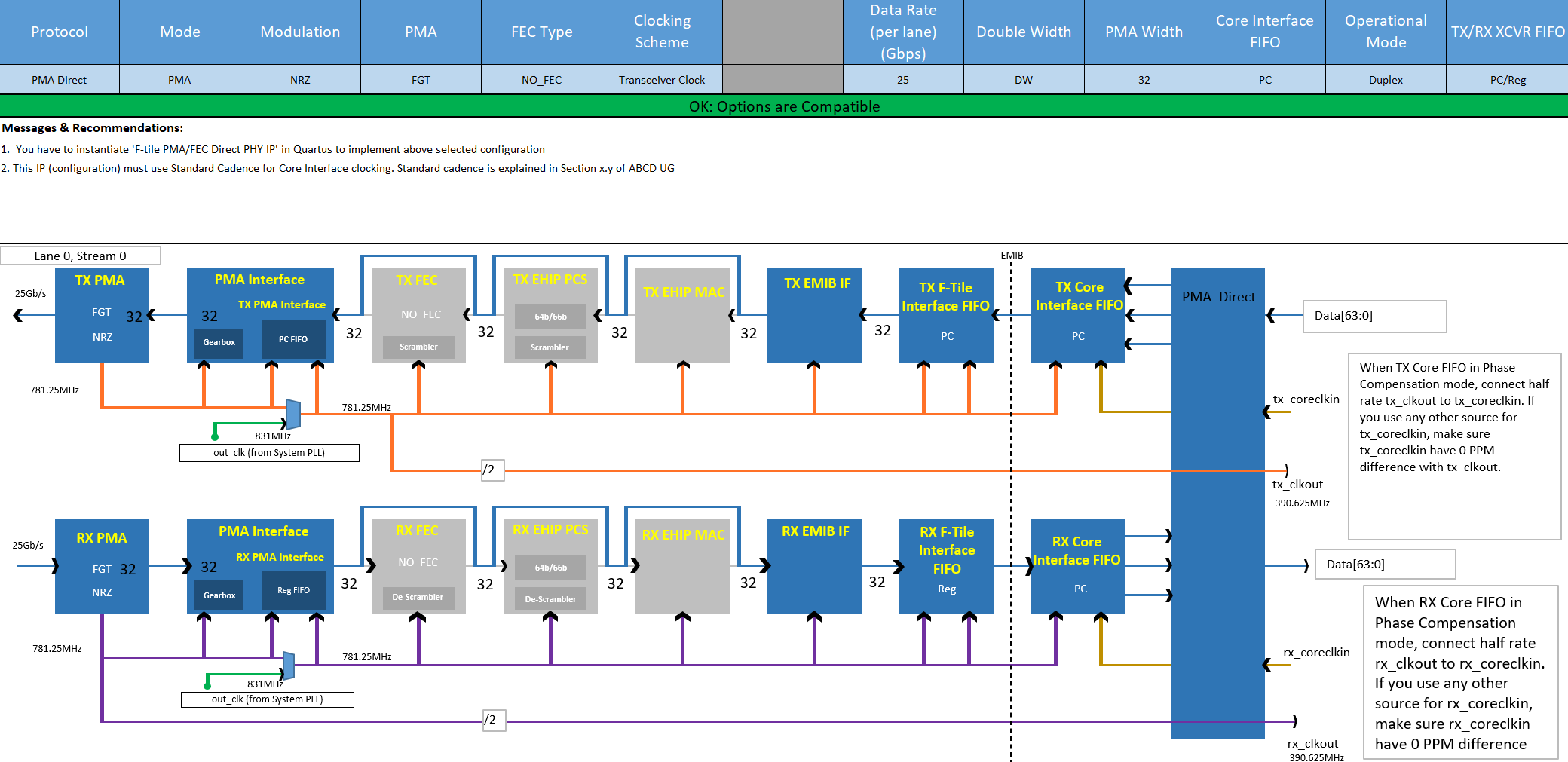
One 25 Gbps PMA Direct PHY IP Port Using the PMA Clocking Mode Example
- All blocks between the PMA interface and core FIFO interface run on the PMA clock.
- On the transmitter, the PMA FIFO interface is clocked by the TX PMA clock on both sides.
- On the receiver, the PMA FIFO interface is clocked by the RX recovered clock on both sides.
- Use the standard cadence. Data on the TX and RX is valid at every clock edge of the PMA clock.
Figure 57. One 25 Gbps PMA Direct PHY IP Port Using the PMA Clocking Mode ExampleThis F-Tile Clocking Tool screenshot shows one 25 Gbps PMA Direct PHY IP port using the PMA clocking mode.
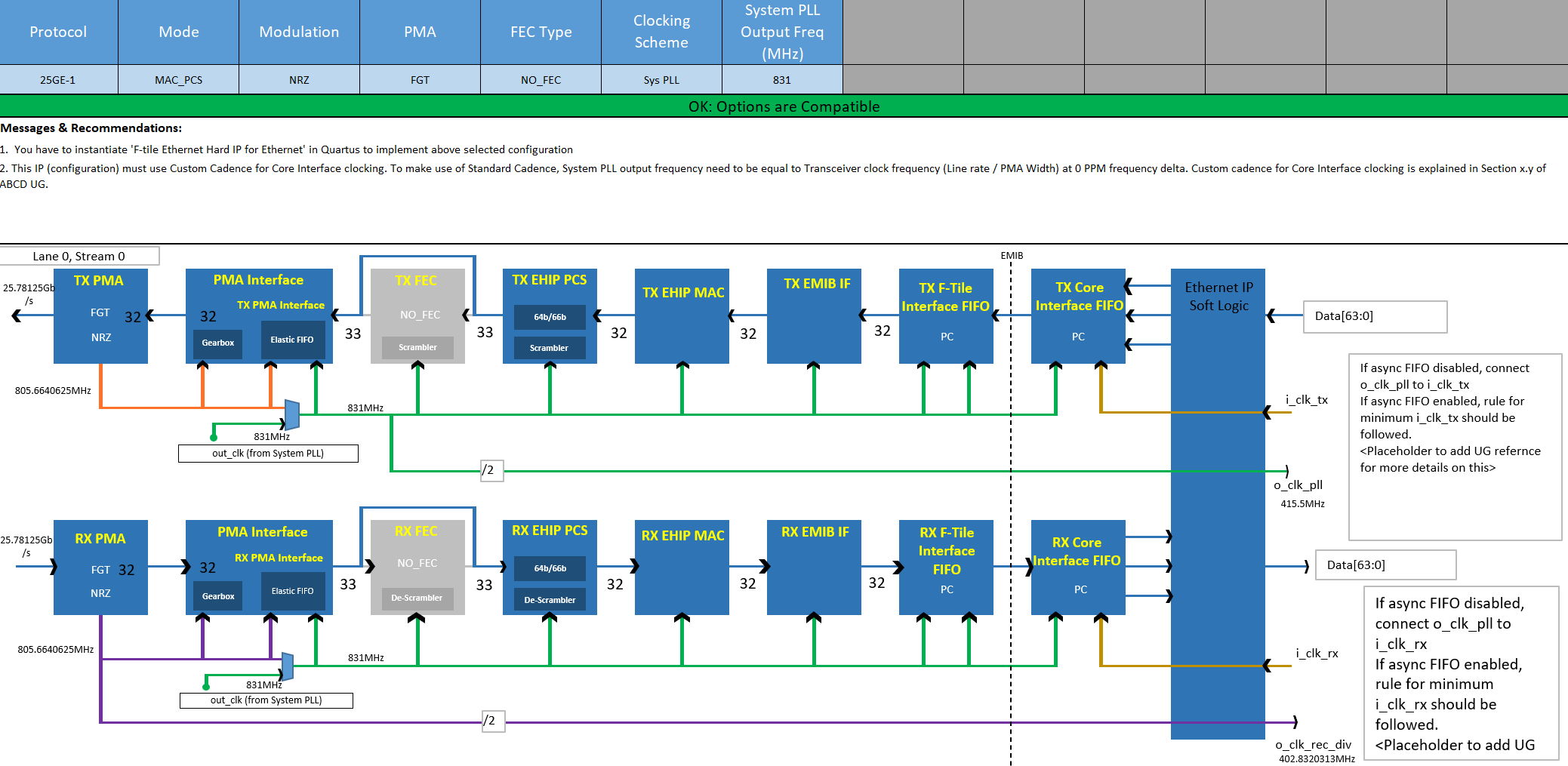
25 Gbps Ethernet Without FEC Port Using the Overclocked System PLL Clocking Mode Example
- All blocks between the PMA interface and core FIFO interface run on the system PLL clock.
- On the transmitter, the PMA FIFO interface performs a clock transfer from the system PLL domain to the TX PMA clock domain.
- On the receiver, the PMA FIFO interface performs a clock transfer from the RX recovered clock domain to the system PLL domain. Refer to F-Tile Ethernet Intel® FPGA Hard IP User Guide for how to clock the core interface.
- Because the system PLL clock frequency is faster than the PMA clock frequency, datapath clocking is overclocked. Therefore, you must use custom cadence.
Figure 58. 25 Gbps Ethernet Without FEC Port Using the Overclocked System PLL Clocking Mode ExampleThis F-Tile Clocking Tool screenshot shows one 25 Gbps Ethernet without FEC port using the overclocked system PLL clocking mode.
15 The TX PMA and TX digital blocks use a PMA clock derived from the local clock. The RX PMA and RX digital blocks run on a recovered clock (the link partner clock).
16 Use Case A: Standard cadence can be used only when the TX PMA reference clock, system PLL reference clock, and link partner TX reference clock are coming from same clock source (with a 0 ppm frequency delta). At 32 Gbps, only the standard cadence can be used because the system PLL reaches a maximum frequency of 1 GHz (it cannot tolerate any difference in the frequencies; the frequency delta must be 0 ppm).
17 Use Case B: The system PLL frequency must be overclocked to compensate for a frequency delta of greater than 0 ppm between the TX PMA reference clock, system PLL reference clock, and link partner TX reference clock. It does not support 32.0 Gbps because the system PLL clock must run at speeds greater than 1 GHz to incorporate a frequency delta of greater than 0 ppm.
18
maximum ppm = maximum ∆ppm ÷ 2
maximum ∆ppm = max(∆ppm between the link partner TX (the recovered clock on the local RX) and system PLL, ∆ppm between the system PLL and TX PMA)
19 The data path clock is already overclocked compared to the PMA clock by approximately 3% because of PCS and FEC overhead. Therefore, a frequency delta of greater than 0 ppm between the TX PMA reference clock, system PLL reference clock, and link partner TX reference clock is allowed.