Visible to Intel only — GUID: jls1512272389760
Ixiasoft
1.1. Acronyms and Definitions
1.2. Recommended System Requirements
1.3. Installation Folders
1.4. Boot Flow Overview
1.5. Getting Started
1.6. Enabling the UEFI DXE Phase and the UEFI Shell
1.7. Using the Network Feature Under the UEFI Shell
1.8. Creating your First UEFI Application
1.9. Using Arm* DS-5* Intel® SoC FPGA Edition (For Windows* Only)
1.10. Pit Stop Utility Guide
1.11. Porting HWLIBs to UEFI Guidelines
1.12. Tera Term Installation
1.13. Minicom Installation
1.14. Win32DiskImager Tool Installation
1.15. TFTPd64 By Ph.Jounin Installation
1.16. Revision History of Intel® Arria® 10 SoC UEFI Boot Loader User Guide
1.5.1. Compiling the Hardware Design
1.5.2. Generating the Boot Loader and Device Tree for UEFI Boot Loader
1.5.3. Building the UEFI Boot Loader
1.5.4. Creating an SD Card Image
1.5.5. Creating a QSPI Image
1.5.6. Booting the Board with SD/MMC
1.5.7. Booting the Board with QSPI
1.5.8. Early I/O Release
1.5.9. Booting Linux* Using the UEFI Boot Loader
1.5.10. Debugging an Example Project
1.5.11. UEFI Boot Loader Customization
1.5.12. Enabling Checksum for the FPGA Image
1.5.13. NAND Bad Block Management
Visible to Intel only — GUID: jls1512272389760
Ixiasoft
1.5.7.5. Booting from VxWorks* Real-Time Operating System from QSPI
- Complete the steps in Updating the Golden Hardware Reference Design to Boot from QSPI, Compiling the Hardware and Software for QSPI and Compiling the UEFI Source Code with the Updated QSPI Device Tree Blob.
- Complete the steps in Programming the VxWorks Real-Time Operating System Image.
- Insert the programmed QSPI daughter card into J23.
- Start a serial terminal program.
- Power up the board. During this time, there is no console output for approximately 15 seconds.
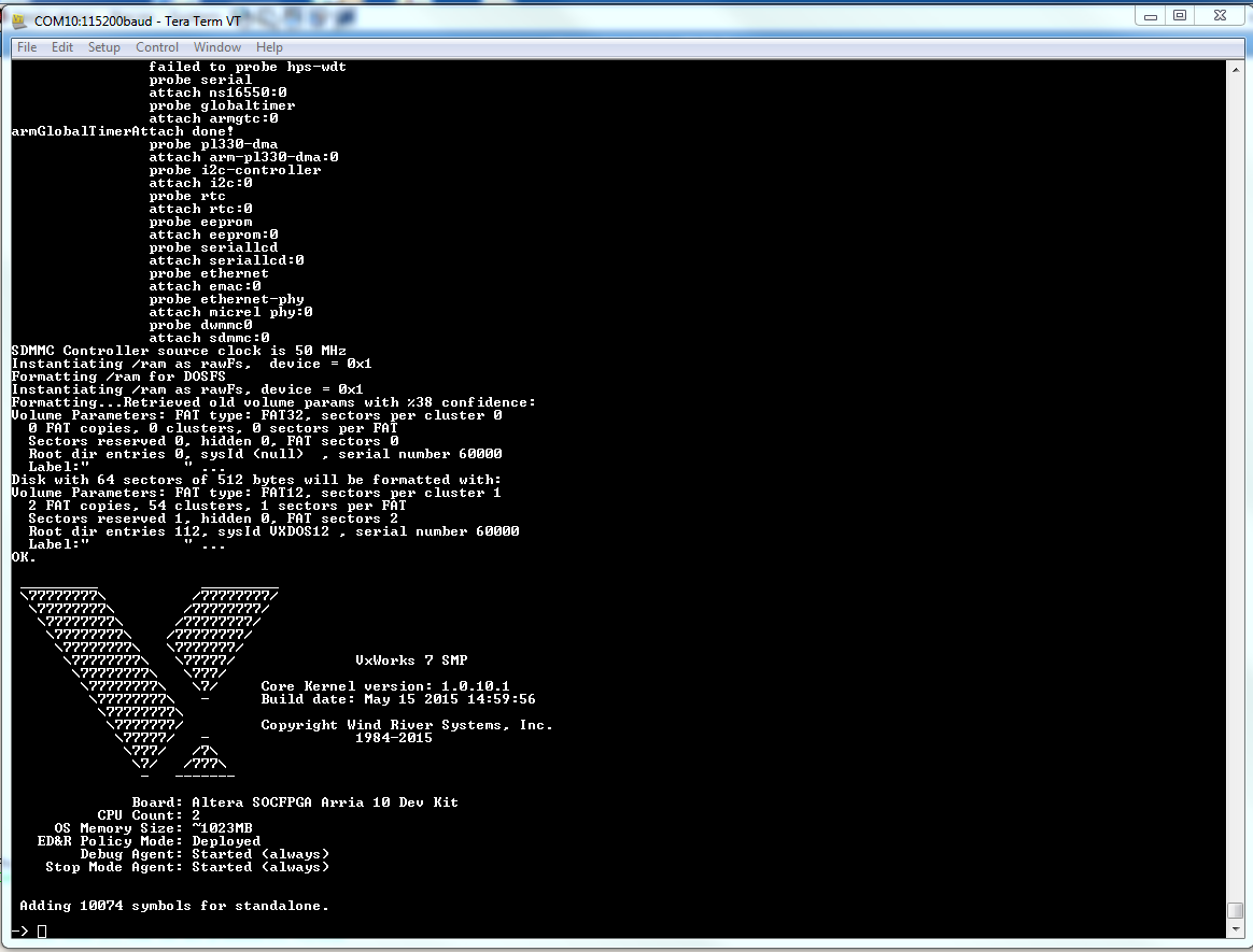
- A series of output messages display on your serial terminal program ending with the following completion message:
Figure 71. VxWorks RTOS Boot Completion Message Output
