Visible to Intel only — GUID: iga1447716926437
Ixiasoft
Visible to Intel only — GUID: iga1447716926437
Ixiasoft
3.3.1. Configuration Options
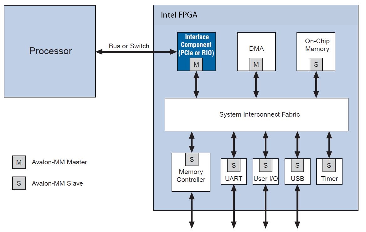
The figure below illustrates a Platform Designer system design that includes a high-performance external bus or switch to connect an industry-standard processor to an external interface of an IP core inside the FPGA. This IP core also includes an Avalon® -MM master port that connects to the Platform Designer system interconnect fabric. As the figure illustrates, Intel provides a library of components, typically Avalon® -MM slave devices, that connect seamlessly to the Platform Designer system interconnect fabric.

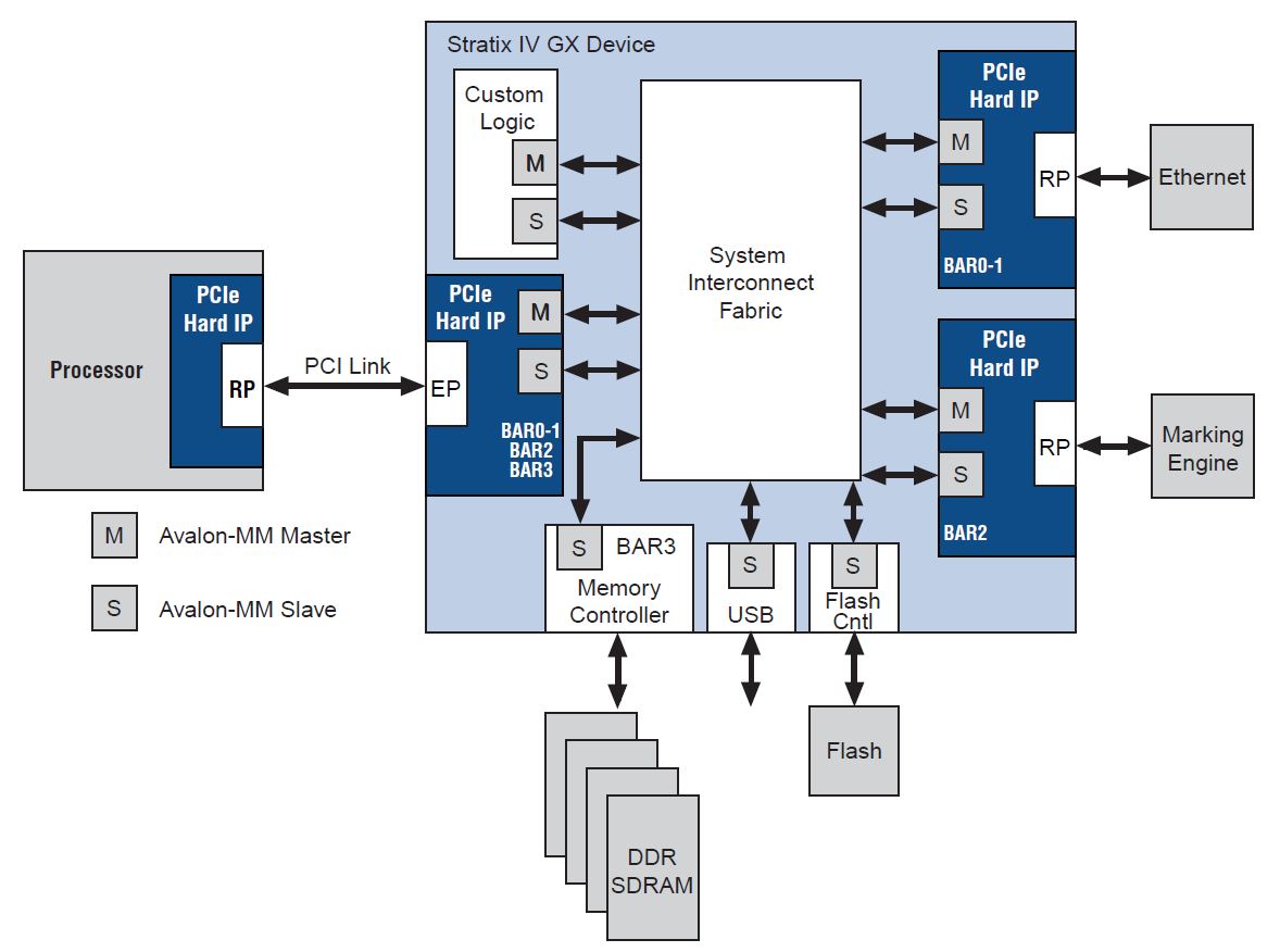
The design below includes an external processor that interfaces to a PCI Express endpoint inside the FPGA. The system interconnect fabric inside the implements a partial crossbar switch between the endpoint that connects to the external processor and two additional PCI Express root ports that interface to an Ethernet card and a marking engine. In addition, the system includes some custom logic, a memory controller to interface to external DDR SDRAM memory, a USB interface port, and an interface to external flash memory. Platform Designer automatically generates the system interconnect fabric to connect the components in the system.

Alternatively, you can also implement your logic in Verilog HDL or VHDL without using Platform Designer. Below the figure illustrates a modular design that uses the FPGA for co-processing with a second module to implement the interface to the processor. If you choose this option, you must write all of the HDL to connect the modules in your system.
The table below summarizes the components Intel provides to connect an Intel FPGA device to an external processor. As this table indicates, three of the components are also available for use in the Parameter Editor design flow in addition to Platform Designer. Alternative implementations of these components are also available through the Intel IP Core Partners Program (DSN) partners. The partners offer a broad portfolio of IP cores optimized for Intel devices.
For a complete list of third-party IP for Intel FPGAs, refer to the Intellectual Property: Find IP web page of the Intel website.
| Protocol | Available in Platform Designer | Available In Parameter Editor | Third-Party Solution | Intel® FPGA IP Evaluation Mode Available |
|---|---|---|---|---|
| RapidIO | Yes | Yes | Yes | Yes |
| PCI Express | Yes | Yes | Yes | Yes |
| PCI Lite | Yes | — | — | License not required |
| SPI | Yes | — | — |
The table below summarizes the most popular options for peripheral expansion in Platform Designer systems that include an industry-standard processor. All of these are available in Platform Designer. Some are also available using the Parameter Editor.
| Protocol | Available in Platform Designer | Available In Parameter Editor | Third-Party Solution | Intel® FPGA IP Evaluation Mode Available |
|---|---|---|---|---|
| CAN | Yes | — | Yes | Yes |
| I2C | Yes | — | Yes | Yes |
| Ethernet | Yes | Yes | Yes | Yes |
| PIO | Yes | — | — | Not required |
| POS-PHY Level 4 (SPI 4.2) | — | Yes | — | Yes |
| SPI | Yes | — | Yes | Not required |
| UART | Yes | — | Yes | Yes |
| USB | Yes | — | Yes | Yes |
For detailed information about the components available in Platform Designer refer to the Embedded Peripherals IP User Guide and the Intellectual Property: Find IP page.
The following sections discuss the high-performance interfaces that you can use to interface to an external processor.