Visible to Intel only — GUID: nfa1438586331775
Ixiasoft
1. Quick Start Guide
2. 10M/100M/1G Ethernet Design Example
3. 1G/2.5G Ethernet Design Example with IEEE 1588v2 Feature
4. 2.5G Ethernet Design Example
5. 10M/100M/1G/2.5G/5G/10G (USXGMII) Ethernet Design Example
6. 10M/100M/1G/2.5G/5G/10G (USXGMII) Ethernet Design Example with IEEE 1588 Design Example
7. Interface Signals Description
8. Configuration Registers Description
9. Low Latency Ethernet 10G MAC Intel® FPGA IP Design Example User Guide: Agilex™ 5 FPGAs and SoCs Archives
10. Document Revision History for the Low Latency Ethernet 10G MAC Intel® FPGA IP Design Example User Guide: Agilex™ 5 FPGAs and SoCs
Visible to Intel only — GUID: nfa1438586331775
Ixiasoft
1.2.1. Procedure
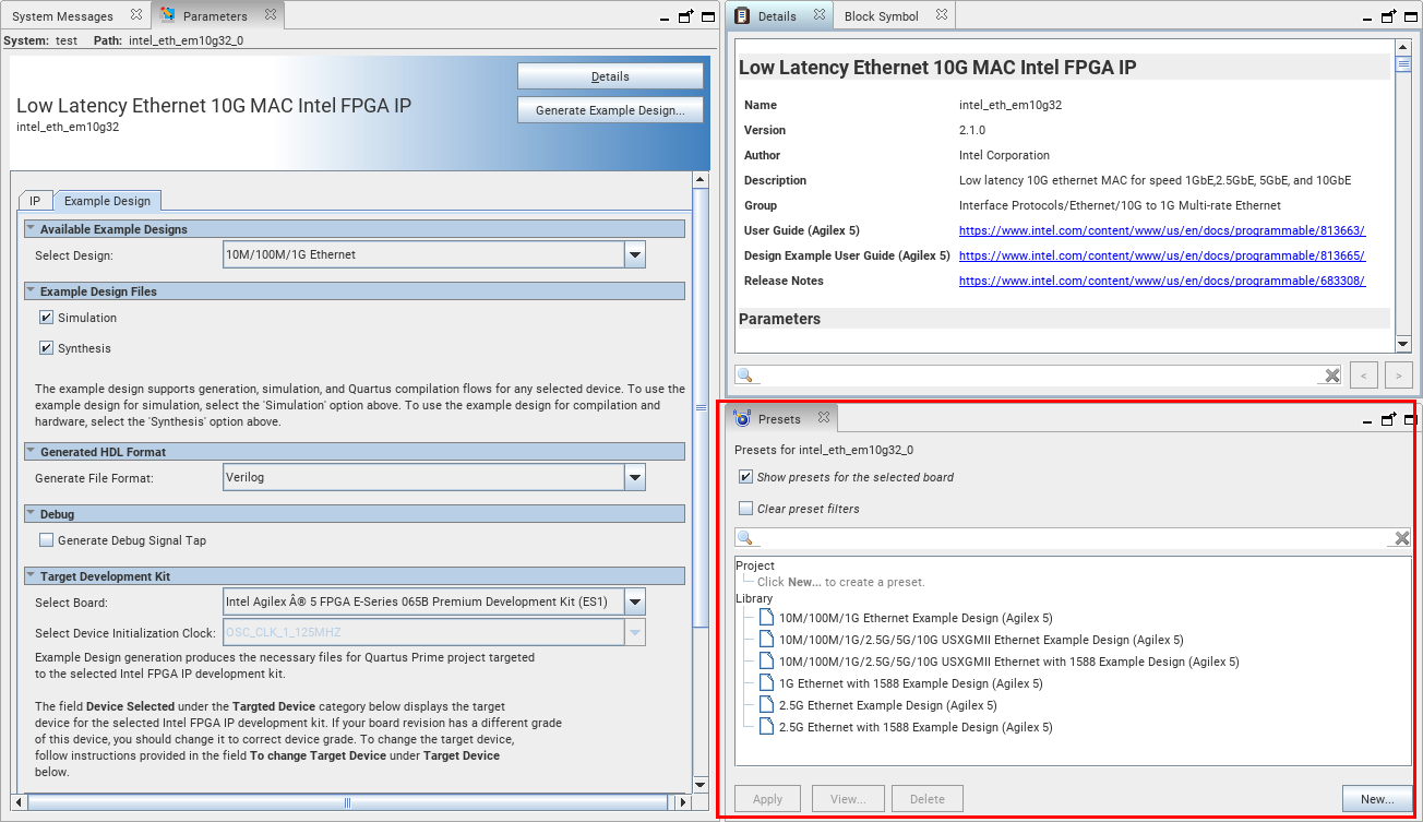
You can generate the design example from the IP Parameter Editor.
Figure 3. Example Design Tab


- In the Quartus® Prime Pro Edition software, click File > New Project Wizard to create a new Quartus Prime project, or File > Open Project to open an existing Quartus Prime project. The wizard prompts you to specify a device.
- Select Agilex™ 5 device family and select a device for your design.
- Click Finish to close the wizard.
- Select Tools > IP Catalog to open the IP Catalog and select Low Latency Ethernet 10G MAC Intel® FPGA IP .
The IP parameter editor appears.
- Specify a top-level name, the folder for your custom IP variation, and the target device. Click OK.
- To generate a design example, select a design example preset from the Presets library and click Apply. When you select a design, the system automatically populates the IP parameters for the design. The parameter editor automatically sets the parameters required to generate the design example. Do not change the preset parameters in the IP tab.
- Specify the parameters in the Example Design tab.
- Click the Generate Example Design.
Note: If the Target Development Kit selected is Agilex™ 5 FPGA E-Series 065B Premium Development Kit (ES1), the device initialization clock is set to OSC_CLK_1_125MHz by default. If None is selected, you must select the available options for the Select Device Initialization Clock. The device initialization clock corresponds to the .qsf file.
The software generates all design files in sub-directories. You require these files to run simulation and compilation.