Visible to Intel only — GUID: uri1666025705860
Ixiasoft
1. About the Agilex™ 7 F-Series and I-Series FPGA Memory Subsystem IP
2. Introduction to Memory Subsystem IP
3. Memory Subsystem IP Architecture and Feature Description
4. Memory Subsystem Features
5. Memory Subsystem Interfaces and Signals
6. Memory Subsystem User Operations
7. Memory Subsystem Register Descriptions
8. Parameterizing the Memory Subsystem IP
9. Simulating a Design Example
10. Document Revision History for Agilex™ 7 F-Series and I-Series FPGA Memory Subsystem IP User Guide
5.3.1. TCAM AXI-ST Request Interface
5.3.2. TCAM AXI-ST Response Interface
5.3.3. TCAM AXI-Lite Interface
5.3.4. BCAM AXI-ST Request Interface
5.3.5. BCAM AXI-ST Response Interface
5.3.6. BCAM AXI-Lite Interface
5.3.7. MBL AXI-ST Request Interface
5.3.8. MBL AXI-ST Response Interface
5.3.9. MBL AXI-Lite Interface
6.4.1. MBL Flush Operation
6.4.2. MBL Insert Key Operation
6.4.3. MBL Delete Key Operation
6.4.4. MBL Lookup Operation Using Key
6.4.5. MBL Modify Operation
6.4.6. MBL Modify Result Using Handle Operation
6.4.7. MBL Delete Key Using Handle Operation
6.4.8. MBL Lookup Using Handle Operation
6.4.9. MBL Insert Key if Not Present or Modify Result if Present Operation
6.4.10. MBL Get Handle Operation
7.2.1. Offset 0x0000 Version
7.2.2. Offset 0x0004 Feature List
7.2.3. Offset 0x0010 Memory Interfaces 0-7
7.2.4. Offset 0x0014 Memory Interfaces 8-15
7.2.5. Offset 0x0018 Memory Interfaces 16-23
7.2.6. Offset 0x001C Memory Interfaces 24-31
7.2.7. Offset 0x0020 Scratch Pad
7.2.8. Offset 0x0030 Control Policy (Lower DWORD)
7.2.9. Offset 0x0034 Control Policy (Upper DWORD)
7.2.10. Offset 0x0038 Read Access Control Policy (Lower DWORD)
7.2.11. Offset 0x003C Read Access Control Policy (Upper DWORD)
7.2.12. Offset 0x0040 Write Access Control Policy (Lower DWORD)
7.2.13. Offset 0x0044 Write Access Control Policy (Upper DWORD)
7.2.14. Offset 0x0050 Memory Status Bitmask 0
7.2.15. Offset 0x0054 Memory Status Bitmask 1
7.2.16. Offset 0x0058 Memory Ready Status 0
7.2.17. Offset 0x005C Memory Ready Status 1
7.2.18. Offset 0x0060 Memory Error Status 0
7.2.19. Offset 0x0064 Memory Error Status 1
7.3.2.1. Version
7.3.2.2. Feature List
7.3.2.3. Interface Attribute Parameters
7.3.2.4. Interface Attribute Parameters 1
7.3.2.5. Scratch Pad
7.3.2.6. General Control (GEN_CTRL)
7.3.2.7. Management Control (MGMT_CTRL)
7.3.2.8. Hash function_0 seed
7.3.2.9. Hash function_1 seed
7.3.2.10. Hash function_2 seed
7.3.2.11. Warning 0 (WARNING_0)
7.3.2.12. Fatal Error (FATAL_ERROR_0)
7.3.2.13. Monitor 0 (MON_)
7.3.2.14. Total Entries (TOTAL_ENTRIES)
7.3.2.15. Max. Rehouse Iterations (Max_Rehouse_Iterations)
7.3.2.16. Statistics Control (STATS_CTRL)
7.3.2.17. Active Table Entries (TABLE_ENTRIES)
7.3.2.18. Key_N
7.3.2.19. Result_N
7.5.1. MBL DFH
7.5.2. General MBL Registers
7.5.3. Version
7.5.4. Mbl_scratch
7.5.5. Mbl_gen_ctrl
7.5.6. Mbl_mgmt_ctrl
7.5.7. Mbl_key_handle
7.5.8. Mbl_nxt_handle_req
7.5.9. Mbl_nxt_handle
7.5.10. Mbl_warning_0
7.5.11. Mbl_fatal_0
7.5.12. Mbl_mon_0
7.5.13. Mbl_total_entries
7.5.14. Mbl_total_rehashes
7.5.15. Mbl_max_used_bins
7.5.16. Mbl_stats_ctrl
7.5.17. Mbl_stats_result
7.5.18. Mbl_max_lkup_latency
7.5.19. Mbl_max_rehash_index
7.5.20. Mbl_key
7.5.21. Mbl_res
8.2.5.1. Parameterizing the External Memory Interface (EMIF) IP
8.2.5.2. Parameterizing the Memory-Specific Adapter
8.2.5.3. Parameterizing the Content-Addressable Memory (CAM) IP
8.2.5.4. Parameterizing the External Memory Interfaces Calibration IP
8.2.5.5. Saving the IPs Within the Memory Subsystem
8.2.5.6. Propagation of Changes Across IPs within the Memory Subsystem IP
Visible to Intel only — GUID: uri1666025705860
Ixiasoft
3.2.2.2. Memory Subsystem TCAM Operations
This topic describes supported TCAM operations.
Insertion
To insert a new entry, a key and mask are needed. The key is first split into a number of chunks. If no bits are masked, then the slice value is used to address a single location and a single bit corresponding to the entry number is set to 1.
If any bits within this slice are set to don’t care (that is, if any bit in the mask is set to 0), then the same operation must be performed by the management logic for all possible values of the don’t care bits.)
Example: Consider the following key slice: 1001 and its corresponding mask value of 1011, which are associated with entry 1. The management logic sets bit number 1 (corresponding to entry 1) at the following addresses of the key RAM for this slice:
- 1001
- 1101
Delete
There are two forms of the delete operation:
- Entry-based – Takes the entry ID as the only argument and deletes an entry by clearing all corresponding bits in all locations of the key RAM for all possible slice values.
- Entry/key/mask-based – Uses information about which slice memory locations must be accessed, based on the key and mask information, and clears only the bits which have previously been set. This generally reduces the time required to delete an entry by reducing the number of memory writes required.
Lookup
Lookup operations can occur as a result of a request from external logic via the AXI ST lookup request interface, or as a result of a management operation initiated by the CPU through the AXI-Lite control register interfaces. The system multiplexes requests from these two sources and sends them through a common pipeline. Internal metadata is used to de-multiplex the lookup results to either the lookup response output or the management block. External lookup requests have higher priority than any management operation.
In the lookup process, the key is divided into slices and each slice is used to address a corresponding memory location in the key RAM. A data word from each RAM slice indicates which entries the corresponding slice value matches.
An AND operation is then applied to the data words from each slice location and the resulting vector indicates the entry matches for all slices of the key.
The core compares the search key against every valid entry in its database, where a key bit is compared only if the entry’s corresponding mask bit is set to 1. This means that an entry with a mask of all zeros will always match every search key; however, because several entries may provide a match, the response only outputs the highest matching entry ID.
Example
The following diagram shows the state of the Key RAM after inserting 5 entries.
Figure 9. TCAM Operation Example
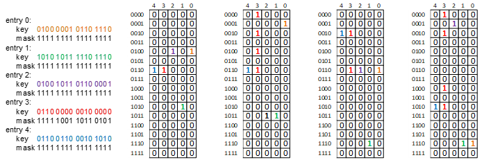
Entries 0, 1, 2 and 4 are expected to match exactly. Entry number 3 has several bits masked out (that is, marked as don’t care by setting the corresponding bit positions to 0.
The following two searches are performed, to illustrate the principle of operation:
Example 1: Lookup key 1010 1011 1110 1110
Figure 10. TCAM Lookup Operation Example 1
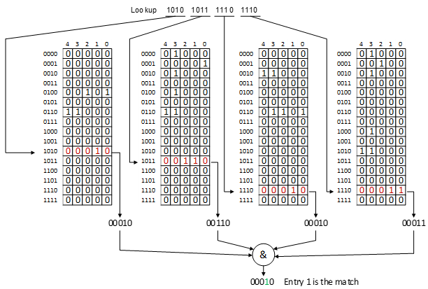
In the above example, there is only one matching entry (entry number 1) and it is an exact match.
Example 2: Lookup key 0110 0110 0010 1010
Figure 11. TCAM Lookup Operation Example 2
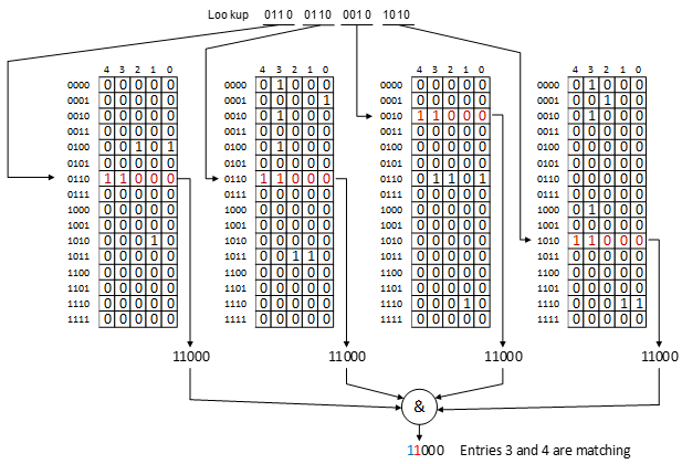
There are two matching entries – entry number 4, which is an exact match, and entry 3, due to its masked bits. If the MS-TCAM is parametrized to operate in standard TCAM mode where the highest matching entry is selected as the output response (GEN_PRIO_RESP = 1), then entry 4 is selected as the matching entry and its entry number appears at the output (along with optional result field). Otherwise, the match vector showing the two matching entries appears as the lookup response.