Agilex™ 7 F-Series and I-Series FPGA Memory Subsystem IP User Guide
Visible to Intel only — GUID: ohw1693483358313
Ixiasoft
Visible to Intel only — GUID: ohw1693483358313
Ixiasoft
8.2.3. Mapping Application to Memory Interfaces (Data Flow)
The Data Flow tab presents a table with checkboxes; the number of columns is equal to the number of memory interfaces which you created, as described in the Defining the Number of Memory Interfaces, Type, and Location topic.
The first row shows the type of Memory interface and its associated identifier, the first column lists all the data structures you need to map to a memory interface, and all the remaining cells of the table have a checkbox that will indicate a connection between the Memory Interface and the application.
The number of rows is dependent on the selected applications in step 2, Storage and Storage for HPS application will generate one row in this table, click on the appropriate checkbox to connect the storage to the desired Memory interface. Note that this type of application can only be matched to an External DDR4 Memory Interface, trying to assign a Storage application to an M20K Memory Interface will result in an error message in the System Messages tab.
The Associative Storage application generates two rows in the Data Flow table, this is due to the requirement of a hash table and a key+result table that CAM IPs use.
When mapping associative storage tables, it's important to consider the following points:
- Mapping a hash table and key+result table to an M20K memory interface - this enables BCAM and TCAM,. You select the desired algorithm and parameterizing the IP after generating the high-level topology and clicking Dive into Packaged Subsystem.
- Mapping a hash table and key+result table to an external DDR4 memory interface – This always infers an MBL, all its parameters are configured after generating the high-level topology and clicking the Dive into Packaged Subsystem.
- It is possible to use two M20K Memory interfaces for the same associative storage application. This is done by assigning the hash table to one interface and the key+result table to another.
- Using two external DDR4 memory interfaces for the same associative storage application is not allowed. Trying to separate the hash table and key+result table across two different EMIF Interfaces results in an error message in the System Messages tab.
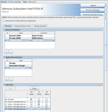
The following figure shows the continuation of the example introduced in the Defining the Number of Memory Interfaces, Type, and Location topic, where three memory interfaces and three applications are selected:
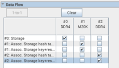
Three memory interfaces are present, and five rows indicate the application data structures to connect. In the example, application #0 is a storage, you can assign it to interface #0 or #2 which are External DDR4. For this case, the application is connected to interface #0. Applications #1 and #2 are associative storage. For each application you can see two rows, one for the hash table and the other for the key+result table. Both rows of application #1 are assigned to interface #1, an M20K memory; this type of connection allows you to select between BCAM and TCAM as the algorithm for this interface. Both rows of application #2 are connected to an external DDR4 memory interface; this is inferred as an MBL IP.