Visible to Intel only — GUID: foz1567781068766
Ixiasoft
1. Getting Started
2. Development Kit Overview
3. Power Up the Development Kit
4. Board Test System (BTS)
5. Development Kit Hardware and Configuration
6. Document Revision History for Intel® Stratix® 10 DX FPGA Development Kit User Guide
A. Development Kit Components
B. Safety and Regulatory Information
C. Compliance and Conformity Information
A.1. Components Overview
A.2. Power, Thermal, and Mechanical Considerations
A.3. Clock Circuits
A.4. Memory Interface
A.5. PCIe Interface
A.6. UPI Interface
A.7. Transceiver Signals: PCIe and UPI Interface
A.8. SlimSAS Connector
A.9. QSFP Network Interface
A.10. I2C Interface
A.11. QSPI Flash Memory
Visible to Intel only — GUID: foz1567781068766
Ixiasoft
A.2.2. Thermal Requirements
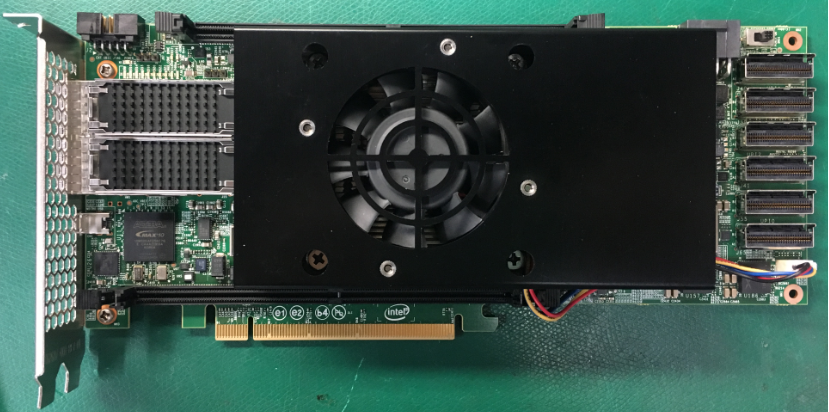
The thermal solution is an active cooling system designed to cool up to 250W total power of the board. The heatsink is designed to meet the height constraints of a 2-slot PCIe card form-factor as defined by the PCIe CEM specification revision 3.0.
The heatsink is securely mounted to the board using screws for easy assembly and removal. The thermal material used between FPGA and heatsink also ensures good thermal contact.
Figure 36. Air-cooled Heatsink Setup

