Visible to Intel only — GUID: gkm1574103467799
Ixiasoft
1. Getting Started
2. Development Kit Overview
3. Power Up the Development Kit
4. Board Test System (BTS)
5. Development Kit Hardware and Configuration
6. Document Revision History for Intel® Stratix® 10 DX FPGA Development Kit User Guide
A. Development Kit Components
B. Safety and Regulatory Information
C. Compliance and Conformity Information
A.1. Components Overview
A.2. Power, Thermal, and Mechanical Considerations
A.3. Clock Circuits
A.4. Memory Interface
A.5. PCIe Interface
A.6. UPI Interface
A.7. Transceiver Signals: PCIe and UPI Interface
A.8. SlimSAS Connector
A.9. QSFP Network Interface
A.10. I2C Interface
A.11. QSPI Flash Memory
Visible to Intel only — GUID: gkm1574103467799
Ixiasoft
4.3.2. Sys Info Tab
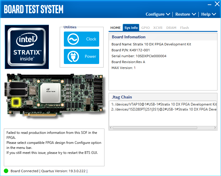
The Sys Info tab shows the board's current configuration. The tab displays the contents of the Intel® MAX® 10 registers, the JTAG chain, the Ethernet port numbers, and other details stored on the board.
Figure 8. Sys Info Tab

The following sections describe the controls of the Sys Info tab.
Board Information
Displays static information about your board:
- Board Name: Indicates the official name of the board given by the BTS.
- Board P/N: Indicates the part number of the board.
- Serial Number: Indicates the serial number of the board.
- Board Revision: Indicates the revision of the board.
- MAX Version: Indicates the version of Intel® MAX® 10 code currently running on the board.
JTAG Chain
Shows devices which are currently in the JTAG chain.