Visible to Intel only — GUID: alo1575315922704
Ixiasoft
1. Getting Started
2. Development Kit Overview
3. Power Up the Development Kit
4. Board Test System (BTS)
5. Development Kit Hardware and Configuration
6. Document Revision History for Intel® Stratix® 10 DX FPGA Development Kit User Guide
A. Development Kit Components
B. Safety and Regulatory Information
C. Compliance and Conformity Information
A.1. Components Overview
A.2. Power, Thermal, and Mechanical Considerations
A.3. Clock Circuits
A.4. Memory Interface
A.5. PCIe Interface
A.6. UPI Interface
A.7. Transceiver Signals: PCIe and UPI Interface
A.8. SlimSAS Connector
A.9. QSFP Network Interface
A.10. I2C Interface
A.11. QSPI Flash Memory
Visible to Intel only — GUID: alo1575315922704
Ixiasoft
4.3.3. GPIO Tab
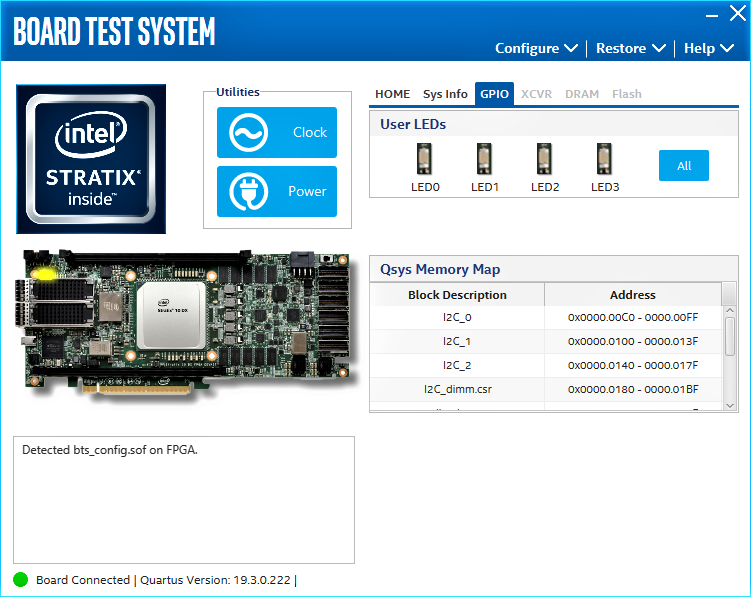
The GPIO tab allows you to interact with all the genral purpose user I/O components on your board. You can turn LEDs on or off.
Figure 9. GPIO Tab

The following sections describe the controls on the GPIO tab:

User LEDs
Displays the current state of user LEDs. Toggle the LED buttons to turn the board LEDs on and off.
Qsys Memory Map
Shows the memory map of the GPIO or FLASH Platform Designer system on your board.