Visible to Intel only — GUID: ahg1626984762976
Ixiasoft
Visible to Intel only — GUID: ahg1626984762976
Ixiasoft
11.9.5.2.5. Address Pattern Examples - Basic Mode
The difference in widths between amm_address_0 and mem_addr is based on the number of symbols per word.
The following points apply to the four examples that follow:
- A value of X indicates that a register is not used, making its value irrelevant.
- The address width (31) is the SYMBOL ADDRESS, as output from the traffic generator. In the design used for these examples, the AMM_WORD_ADDRESS_WIDTH is 26 bits. To account for this difference, the traffic generator shifts all addresses by the difference (5 bits). The examples below use this shifted address, but the external memory interface does not see this shift on its side of the ctrl_amm interface.
- The provided waveform is only a snippet of the full instruction pattern, to demonstrate the write instructions and the corresponding addresses. Not all read blocks are shown, due to space restrictions.
The width of the Avalon® address is based on the following:
- The data width on the memory side.
- Whether a configured EMIF IP is quarter rate, half rate, or full rate.
- Whether the memory interface is double data rate or quarter data rate.
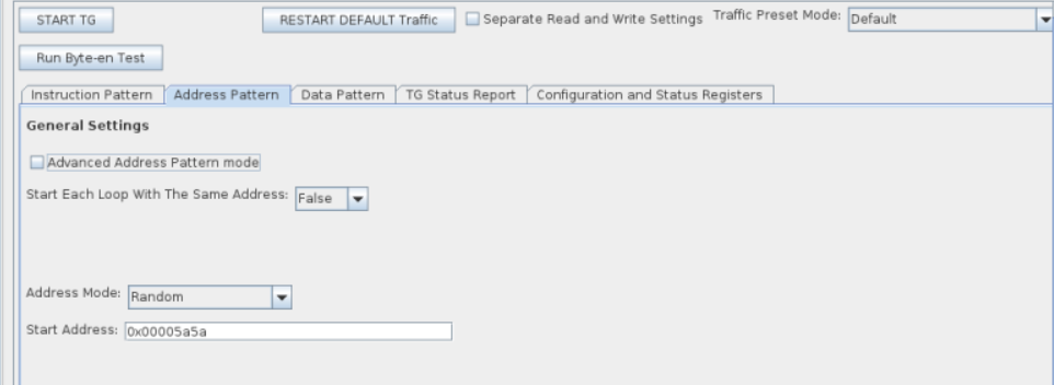
Example 1: Random Address Mode
Consider the following instruction pattern:
TG_LOOP_COUNT=2 TG_WRITE_REPEAT_COUNT=1 TG_RW_GEN_IDLE_COUNT=2
TG_WRITE_COUNT=3 TG_READ_REPEAT_COUNT=1 TG_RW_GEN_LOOP_IDLE_COUNT=0
TG_READ_COUNT=3 TG_BURST_LENGTH=1

This configuration can be performed in basic mode. For the equivalent traffic pattern in advanced mode see example 1 in Address Pattern Examples - Advanced Mode.

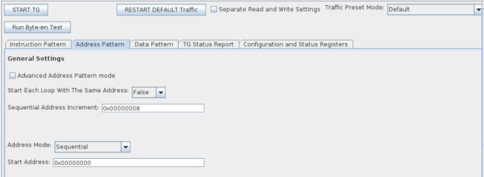
Example 2: Sequential Address Mode
Consider the following instruction pattern:
TG_LOOP_COUNT=2 TG_WRITE_REPEAT_COUNT=1 TG_RW_GEN_IDLE_COUNT=0
TG_WRITE_COUNT=3 TG_READ_REPEAT_COUNT=1 TG_RW_GEN_LOOP_IDLE_COUNT=1
TG_READ_COUNT=3 TG_BURST_LENGTH=1

This configuration can be performed in basic mode. For the equivalent traffic pattern in advanced mode see example 2 in Address Pattern Examples - Advanced Mode.

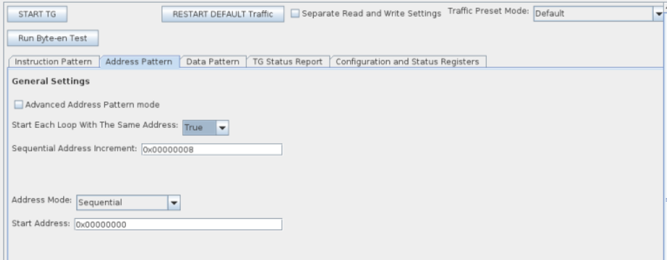
Example 3: Sequential Address Mode with TG_RETURN_TO_START_ADDR=1
Consider the following instruction pattern:
TG_LOOP_COUNT=2 TG_WRITE_REPEAT_COUNT=1 TG_RW_GEN_IDLE_COUNT=0
TG_WRITE_COUNT=3 TG_READ_REPEAT_COUNT=1 TG_RW_GEN_LOOP_IDLE_COUNT=1
TG_READ_COUNT=3 TG_BURST_LENGTH=1

This configuration can be performed in basic mode. For the equivalent traffic pattern in advanced mode see example 3 in Address Pattern Examples - Advanced Mode.

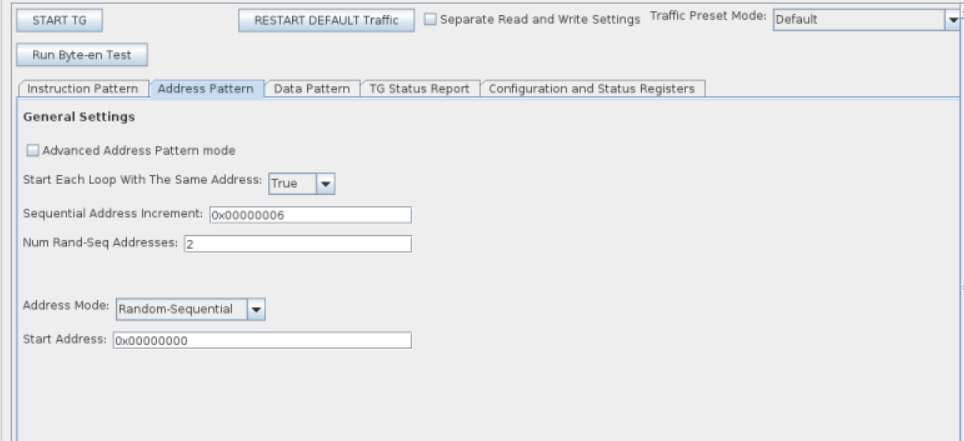
Example 4: Random Sequential Address Mode
Consider the following instruction pattern:
TG_LOOP_COUNT=1 TG_WRITE_REPEAT_COUNT=1 TG_RW_GEN_IDLE_COUNT=1
TG_WRITE_COUNT=8 TG_READ_REPEAT_COUNT=1 TG_RW_GEN_LOOP_IDLE_COUNT=1
TG_READ_COUNT=8 TG_BURST_LENGTH=1

The goal of this address pattern is to create a random sequential pattern with the bottom 4 bits of the address incrementing sequentially by 6 every cycle, while the upper bits are randomly generated every-other cycle.
This configuration can be performed in basic mode. It automatically calculates the value for TG_ADDR_FIELD_MSB_INDEX+1 to ensure that a sufficient number of bits are reserved for field 0 based on the sequential address increment, num rand-seq addresses, burst length, and word-address-divisible-by values. For the equivalent traffic pattern in advanced mode, refer to example 4 in Address Pattern Examples - Advanced Mode.
