Visible to Intel only — GUID: lro1424384653103
Ixiasoft
1.1. Introduction
1.2. Bare Metal Overview
1.3. Prerequisites for the Bare Metal Development Environment
1.4. Bare Metal Compiler
1.5. Bare Metal Development Flow
1.6. Using DS-5 AE to Create and Manage Bare Metal Projects
1.7. Importing, Building and Debugging in a Make-Based Example
1.8. DS-5 ARM HWLIBs Project Derived from Make-Based Project
1.9. Minimal Preloader
1.10. Appendix: Troubleshooting
Visible to Intel only — GUID: lro1424384653103
Ixiasoft
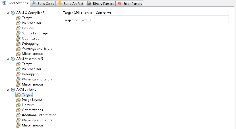
1.8.1.2.1.2. ARM Linker Settings
- Define the “Target CPU (--cpu)” as “Cortex-A9” in the Target section.
Figure 61. ARM Linker Target Settings
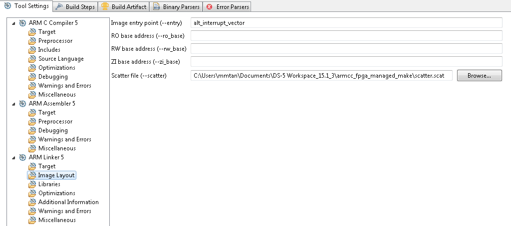
- "Define the Image entry point (--entry) as "alt_interrupt_vector" and add the Scatter file (--scatter) location in the "Image Layout" section.
Figure 62. ARM Linker Image Layout Settings
- Leave “Libraries”, “Optimization”, “Additional Information”, and “Warnings and Errors” with default values.
- Add the FPGA object file in the Miscellaneous settings section.
- Click on the Add... icon and Browse to the location of the FPGA object file under the "armcc_fpga_managed_make" Workspace.
Figure 63. ARM Linker Miscellaneous Settings
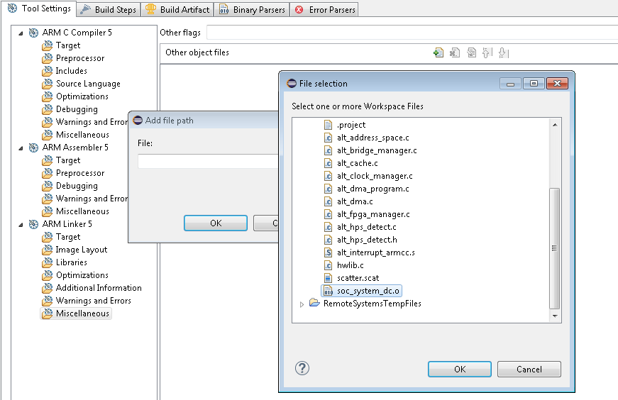 Figure 64. ARM Linker Miscellaneous Settings - Part 2
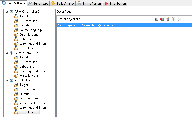
- Click Apply and then OK to apply settings and return.