Visible to Intel only — GUID: dlo1612911015909
Ixiasoft
1. List of Abbreviations
2. Introduction
3. Intel® Stratix® 10 FPGA Package Mechanical Design
4. Intel® Stratix® 10 FPGA Thermal Design Parameters
5. Thermal Design Process for Intel® Stratix® 10 Devices
6. Power and Thermal Calculator (PTC) for Intel® Stratix® 10 Devices
7. Maximum Power and Typical Power
8. Document Revision History for AN 943: Thermal Modeling for Intel® Stratix® 10 FPGAs with the Intel® FPGA Power and Thermal Calculator
6.1. Device Selection
6.2. Logic Design Information
6.3. Thermal Settings and Parameters
6.4. Thermal Design Optimization
6.5. Updating Thermal Parameters
6.6. Intel® Stratix® 10 Device with PCIe Thermal Design Example 1
6.7. Heat Sink
6.8. Intel® Stratix® 10 Device with PCIe Thermal Design Example 2 (Alternate Method)
Visible to Intel only — GUID: dlo1612911015909
Ixiasoft
3.1. Intel® Stratix® 10 Physical Package Structure
Figure 1. Physical Package StructureThis is a typical package structure relevant to thermal analysis and as laid out in the compact thermal models. This package only shows the core fabric die and transceiver dies.
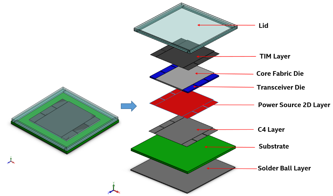
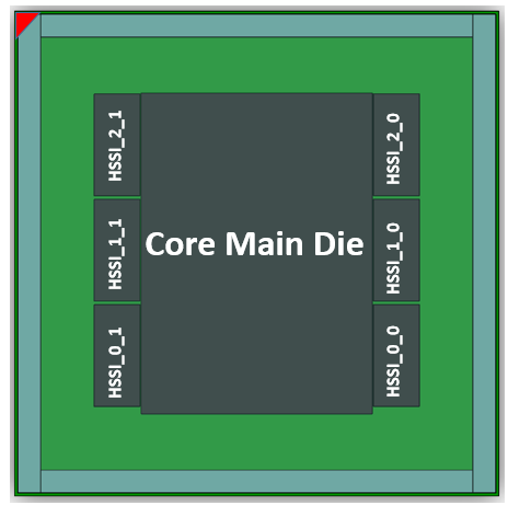
Figure 2. Package Top View