Visible to Intel only — GUID: kka1612998661845
Ixiasoft
1. List of Abbreviations
2. Introduction
3. Intel® Stratix® 10 FPGA Package Mechanical Design
4. Intel® Stratix® 10 FPGA Thermal Design Parameters
5. Thermal Design Process for Intel® Stratix® 10 Devices
6. Power and Thermal Calculator (PTC) for Intel® Stratix® 10 Devices
7. Maximum Power and Typical Power
8. Document Revision History for AN 943: Thermal Modeling for Intel® Stratix® 10 FPGAs with the Intel® FPGA Power and Thermal Calculator
6.1. Device Selection
6.2. Logic Design Information
6.3. Thermal Settings and Parameters
6.4. Thermal Design Optimization
6.5. Updating Thermal Parameters
6.6. Intel® Stratix® 10 Device with PCIe Thermal Design Example 1
6.7. Heat Sink
6.8. Intel® Stratix® 10 Device with PCIe Thermal Design Example 2 (Alternate Method)
Visible to Intel only — GUID: kka1612998661845
Ixiasoft
6.6. Intel® Stratix® 10 Device with PCIe Thermal Design Example 1
This topic explores the computational fluid dynamic (CFD) analysis of a 1SM21BE Intel® Stratix® 10 device on a two-slot PCIe board. For simplicity, this topic assumes that the FPGA is the only active device on the circuit board.
- The first step in the thermal design process is to enter design parameters into the Intel® FPGA Power and Thermal Calculator (PTC) and obtain the thermal parameters. For details on this step, refer to Power and Thermal Calculator (PTC), earlier in this document.
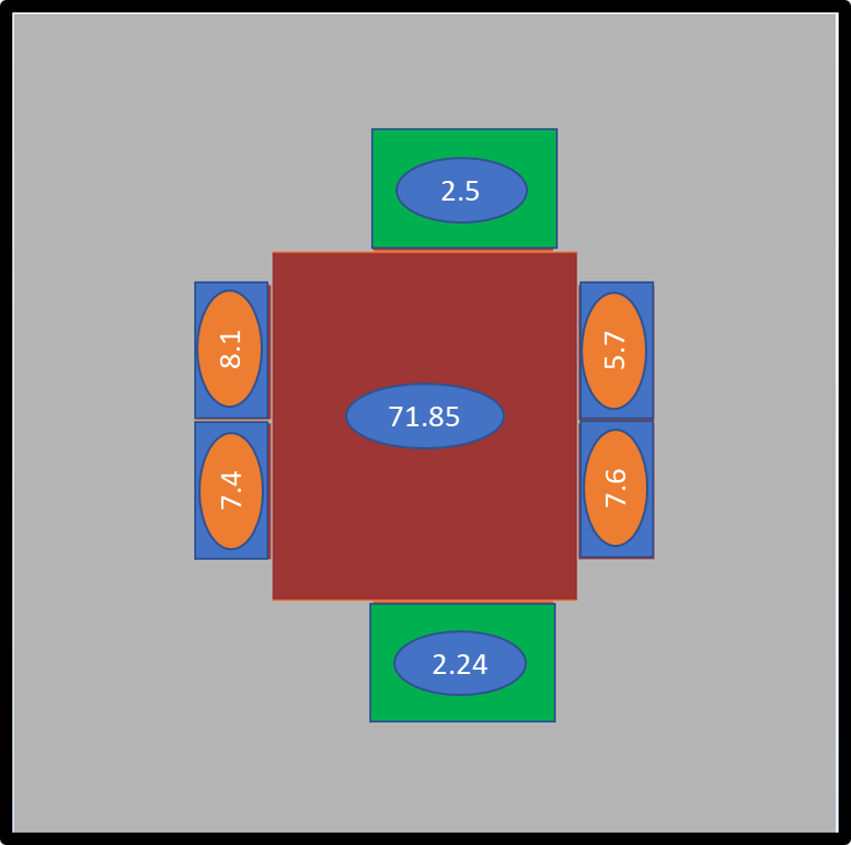
- The second step is to obtain the Compact Thermal Model (CTM) for the Intel® Stratix® 10 device. The figure below shows the device layout. We take the device to our CFD model and assign the powers to the dies as shown below.
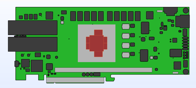
Figure 11. Die Power Assignment for CFD AnalysisThe figure below illustrates the board layout in the CFD model.
 Figure 12. Die Power Assignment for CFD Analysis
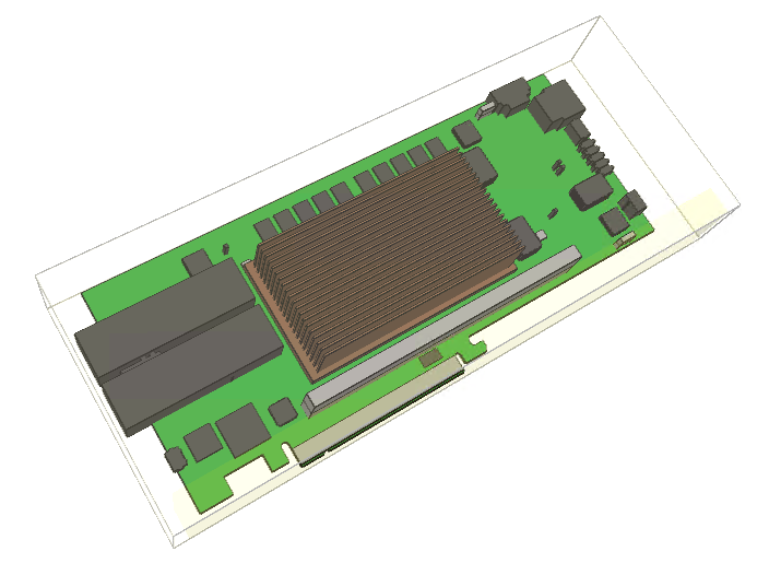
 Figure 13. CFD Model