Visible to Intel only — GUID: hdu1709856534060
Ixiasoft
1. Introduction to Agilex™ 5 FPGA Thermal Design Guidelines
2. Agilex™ 5 FPGA Mechanical Construction
3. Agilex™ 5 FPGA CTM Construction
4. Power and Thermal Calculator (PTC)
5. General FPGA Thermal Design Considerations
6. Design Examples
7. Heat Sinks
8. Document Revision History for the Thermal Design User Guide: Agilex™ 5 FPGAs
A. Agilex™ 5 FPGA Product Keys and Package Drawings
Visible to Intel only — GUID: hdu1709856534060
Ixiasoft
4.5. Sensor Temperatures on the PTC Thermal Tab
The temperature limit of each built-in sensor in the FPGA is calculated per design and is shown in the Thermal tab of the PTC.
In the Thermal tab figure below, the table of sensor values is marked in red.
Figure 4. PTC Thermal Tab, Case and Thermal Sensor Temperatures
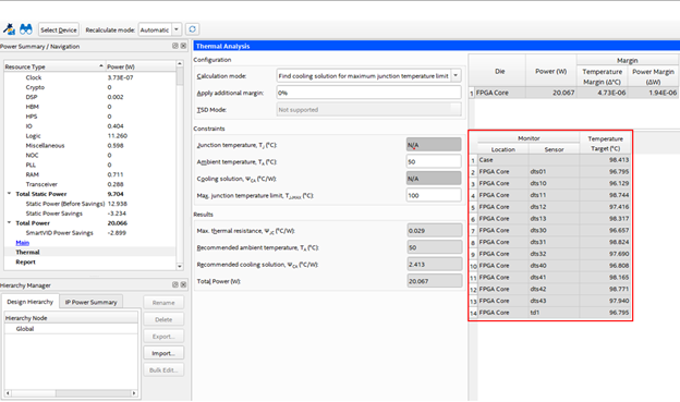
The case and sensor temperature limits in the above figure are for a design using an Agilex™ 5 A5ED0655BB32A part. These values correspond to a TJ-MAX of 100⁰ C in this case. As shown, none of the sensors coincide with the hot spot of the FPGA die; therefore, all sensor temperatures are less than 100⁰ C. If any of these sensors report a value higher than the ones in the table, that indicates that TJ-MAX has exceeded the target of 100° C.
For example. in this case, if your control system is monitoring sensors dts01 and td1, the cooling system must provide sufficient cooling to keep both sensor temperature below 96.8° C. Otherwise the TJ-MAX will exceed the target of 100° C.
Temperatures exceeding these values also indicate that the FPGA power exceeds the PTC prediction; this could happen if there is insufficient cooling or if design factors have changed.