A newer version of this document is available. Customers should click here to go to the newest version.
Visible to Intel only — GUID: wqg1706074221751
Ixiasoft
Visible to Intel only — GUID: wqg1706074221751
Ixiasoft
6.1. Example 1: Constant Die Power with CFD and TJ-MAX Calculation Mode
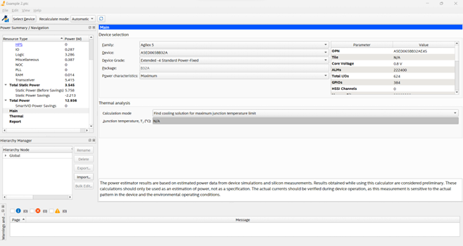
This example uses an Agilex™ 5 FPGA, part number A5ED065BB32A and CTM file ctm-A5E-065-B32.
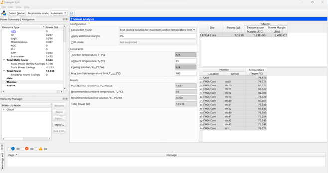
The following figures illustrate the Main and Thermal tabs in the PTC. The total power dissipation in this application is about 13 watts and the PTC calculates a TCASE value of 78.5⁰ C, so the TJ-MAX does not exceed 100⁰ C.
You can enter any value for the TJ-MAX on the Thermal tab. This value depends primarily on your design goals, such as product life, power dissipation, or creating margins for future additions to the design.
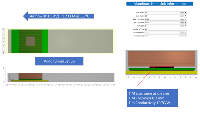
For thermal analysis, this example assumes a heat sink with the same footprint as the FPGA device and a ducted cooling channel to simplify the analysis. The following figure illustrates the stack-up in the wind tunnel.