Visible to Intel only — GUID: nyo1706072773271
Ixiasoft
1. Introduction to Agilex™ 5 FPGA Thermal Design Guidelines
2. Agilex™ 5 FPGA Mechanical Construction
3. Agilex™ 5 FPGA CTM Construction
4. Power and Thermal Calculator (PTC)
5. General FPGA Thermal Design Considerations
6. Design Examples
7. Heat Sinks
8. Document Revision History for the Thermal Design User Guide: Agilex™ 5 FPGAs
A. Agilex™ 5 FPGA Product Keys and Package Drawings
Visible to Intel only — GUID: nyo1706072773271
Ixiasoft
4.1. PTC Thermal Tab Parameters
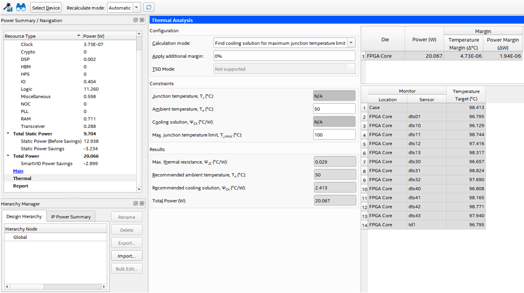
The Thermal tab of the PTC is where you input relevant thermal parameters for your design, and find the output needed for the thermal analysis.
Figure 3. PTC Thermal Tab
| Parameter | Description |
|---|---|
| TA (⁰ C) | Ambient temperature, measured locally surrounding the FPGA. Measure the ambient temperature just upstream of a passive heat sink or at the fan inlet for an active heat sink. This value affects the junction temperature of the main FPGA core fabric die and its power dissipation. |
| TJ-MAX (⁰ C) | By default, the PTC sets this value to 100 ⁰C when the PTC calculation mode is set to Find a cooling solution for Maximum junction temperature limit. However, note that you can change this value and set your own target maximum temperature. Also, the PTC can calculate this value if the calculation mode is set to Find available thermal margin for cooling solution. |
| TCASE (⁰ C) | The temperature at the top of the exposed die. For a design to not exceed its TJ-MAX, the cooling solution must be able to maintain the TCASE temperature at or below the TCASE temperature reported by the PTC. |
| Power (W) | Power dissipation of the die. |
| Temperature Margin (⁰ C) | When the available cooling solution keeps the TJ-MAX below the set design goal , the PTC shows the difference as the Temperature Margin. |
| Power Margin (⁰ C) | When the available cooling is more than necessary to maintain the TJ-MAX below the design goal, the PTC calculates how much additional power can be added to the design before the design goal is reached. This additional capacity is the Power Margin. |
| ΨJC (⁰ C/W) | The thermal resistance between the hot spot on the die and the top center of the die. The ΨJC value is calculated by this equation: ΨJC=(TJ-MAX-TCASE)/ Power Note:ΨJC values are not constant for a specific package and change as the FPGA resource usage changes. |
| ΨCA (⁰ C/W) | The thermal resistance between the top center of the exposed die and the ambient ΨCA can be used as a figure of merit in assessing the required cooling solution for a design. For example, the lower the ΨCA value, the more aggressive cooling solution is needed. The value of ΨCA is calculated by this equation: ΨCA = (TCASE - TA) / Power
Note: ΨCA values are not constant for a specific package and change as the FPGA resource and ambient temperature changes. You must recalculate this value for each design.
|