Visible to Intel only — GUID: hve1696518179730
Ixiasoft
Visible to Intel only — GUID: hve1696518179730
Ixiasoft
5.3.1. 1:1 Connectivity with EMIF and HBM
With this recommendation in mind, two topologies are possible when combining EMIF and HBM:
- Using a direct (straight) connection of the EMIF.
or
- Using the outermost initiators for the EMIF.
The following figures illustrate these two configurations and show how the direct (straight) connection topology is beneficial for EMIF.
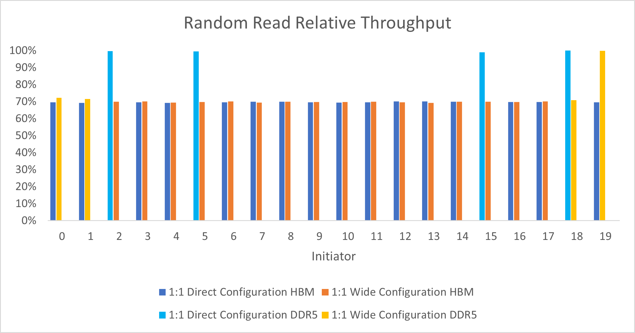
When tested with sequential access, both topologies can achieve the maximum possible throughput of Intel Agilex® 7 M-Series FPGAs. However, when tested with random access traffic, the advantages of direct connection become apparent.

The direct EMIF topology allows higher throughput on the EMIF initiators, as Random Read Relative Throughput illustrates. This configuration achieves higher throughput because EMIF and HBM have different performance characteristics when presented with non-sequential access traffic. In the EMIF wide initiator placement example, what would normally be higher performance by the EMIF is reduced by congestion of the HBM traffic on the NoC links. Notice how the connection on the rightmost side shows higher performance because the connection does not overlap with any HBM traffic.
Conversely, in the topology with the EMIF connected over direct links, the EMIF traffic does not have any interaction with the slower HBM traffic. Therefore, all four EMIFs show higher performance.
Use the direct links for EMIF traffic to separate the link from HBM traffic, and to avoid affecting one source of traffic with another. You can generalize this guideline to other cases where you use different HBM targets with different traffic patterns. Separate traffic with reduced performance characteristics from traffic with better performance characteristics.
Link 0 and Link 1 Detail shows the details of Link 0 and Link 1. You can see that the leftmost initiator connection overlaps with the other EMIF connection. This EMIF connection is congested because it overlaps with one of the congested HBM connections.