Visible to Intel only — GUID: hve1696518179730
Ixiasoft
1. Answers to Top FAQs
2. About This Application Note
3. Component Bandwidth Projections and Limitations
4. Resource Planning for Intel Agilex® 7 M-Series FPGAs
5. Factors Affecting NoC Performance
6. Debugging the NoC
7. Document Revision History of AN 1003: Multi Memory IP System Resource Planning for Intel Agilex® 7 M-Series FPGAs
4.1. Hard Memory NoC Resource Planning Overview
4.2. I/O Bank Blockage
4.3. Planning Avalon® Streaming Utilization
4.4. Planning for Initiator Blockage Impact from GPIO, LVDS SERDES, and PHY Lite Bypass Mode
4.5. Planning NoC PLL and I/O PLL
4.6. Pin Planning for HPS EMIF
4.7. Planning for an External Memory Interface
4.8. Planning for HBM2E
4.9. Planning for the Fabric NoC
4.10. Planning for AXI4-Lite
4.11. Planning NoC and Memory Solution Clocks
5.1. Recommended Performance Tuning Procedure
5.2. NoC Initiator and Target Clock Rate
5.3. Recommended NoC Design Topologies
5.4. Traffic Access Pattern and Memory Controller Efficiency
5.5. Traffic Access Pattern Due To Multiple Traffic Flows
5.6. Transaction Size
5.7. Congestion Interaction
5.8. Bandwidth Sharing At Each Switch
5.9. Exceeding NoC Bandwidth Limits
5.10. Maximum Number of Outstanding Transactions
5.11. QoS Priority
5.12. AxID
5.13. Example: 2x2 HBM Crossbars
5.14. Example: 16x16 Crossbar
Visible to Intel only — GUID: hve1696518179730
Ixiasoft
5.3.1. 1:1 Connectivity with EMIF and HBM
When connecting all of the HBM and External Memory Interface (EMIF) targets in a 1:1 configuration (one initiator accesses each target), the optimal configuration is to fan-out traffic symmetrically from the center of the HBM to avoid overloading the NoC.
With this recommendation in mind, two topologies are possible when combining EMIF and HBM:
- Using a direct (straight) connection of the EMIF.
or
- Using the outermost initiators for the EMIF.
The following figures illustrate these two configurations and show how the direct (straight) connection topology is beneficial for EMIF.
Figure 14. HBM and EMIF with 1:1 Connections and Direct Connection for EMIF
Figure 15. HBM and EMIF with 1:1 Connections and Wide Initiator Placement for EMIF
When tested with sequential access, both topologies can achieve the maximum possible throughput of Intel Agilex® 7 M-Series FPGAs. However, when tested with random access traffic, the advantages of direct connection become apparent.
Figure 16. Random Read Relative Throughput
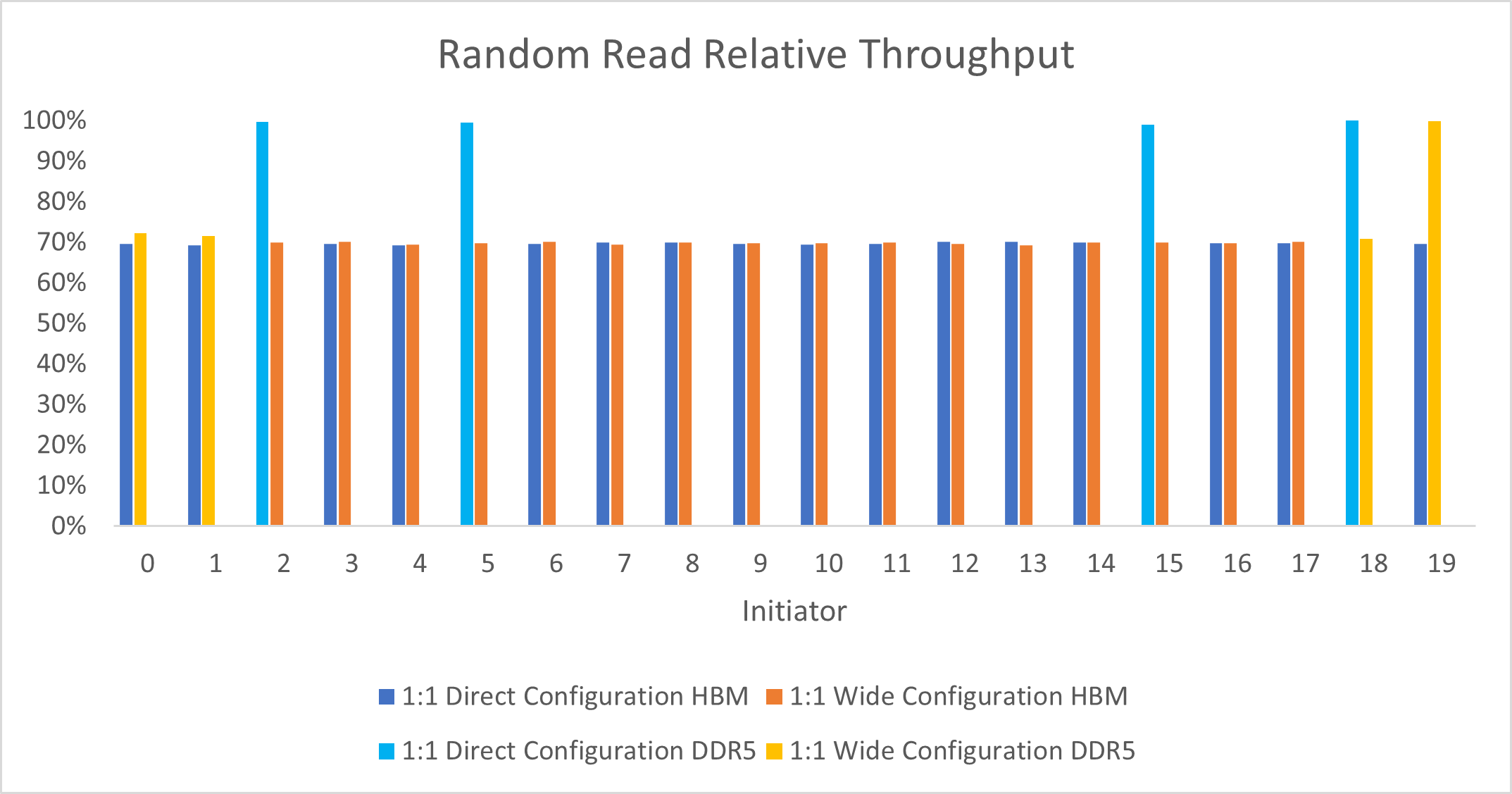
The direct EMIF topology allows higher throughput on the EMIF initiators, as Random Read Relative Throughput illustrates. This configuration achieves higher throughput because EMIF and HBM have different performance characteristics when presented with non-sequential access traffic. In the EMIF wide initiator placement example, what would normally be higher performance by the EMIF is reduced by congestion of the HBM traffic on the NoC links. Notice how the connection on the rightmost side shows higher performance because the connection does not overlap with any HBM traffic.
Conversely, in the topology with the EMIF connected over direct links, the EMIF traffic does not have any interaction with the slower HBM traffic. Therefore, all four EMIFs show higher performance.
Use the direct links for EMIF traffic to separate the link from HBM traffic, and to avoid affecting one source of traffic with another. You can generalize this guideline to other cases where you use different HBM targets with different traffic patterns. Separate traffic with reduced performance characteristics from traffic with better performance characteristics.
Figure 17. Leftmost Initiator in Wide Initiator Placement ConfigurationIn the wide initiator placement configuration, you can observe that the leftmost target and initiator connection does not overlap with the slower HBM traffic in the example. Even so, this connection still experiences a slowdown. This slowdown is because the connection second from the left is impacted by HBM traffic, and therefore also becomes congested.
Link 0 and Link 1 Detail shows the details of Link 0 and Link 1. You can see that the leftmost initiator connection overlaps with the other EMIF connection. This EMIF connection is congested because it overlaps with one of the congested HBM connections.
Figure 18. Link 0 and Link 1 Detail