Visible to Intel only — GUID: cfr1697648343987
Ixiasoft
1. Answers to Top FAQs
2. About This Application Note
3. Component Bandwidth Projections and Limitations
4. Resource Planning for Intel Agilex® 7 M-Series FPGAs
5. Factors Affecting NoC Performance
6. Debugging the NoC
7. Document Revision History of AN 1003: Multi Memory IP System Resource Planning for Intel Agilex® 7 M-Series FPGAs
4.1. Hard Memory NoC Resource Planning Overview
4.2. I/O Bank Blockage
4.3. Planning Avalon® Streaming Utilization
4.4. Planning for Initiator Blockage Impact from GPIO, LVDS SERDES, and PHY Lite Bypass Mode
4.5. Planning NoC PLL and I/O PLL
4.6. Pin Planning for HPS EMIF
4.7. Planning for an External Memory Interface
4.8. Planning for HBM2E
4.9. Planning for the Fabric NoC
4.10. Planning for AXI4-Lite
4.11. Planning NoC and Memory Solution Clocks
5.1. Recommended Performance Tuning Procedure
5.2. NoC Initiator and Target Clock Rate
5.3. Recommended NoC Design Topologies
5.4. Traffic Access Pattern and Memory Controller Efficiency
5.5. Traffic Access Pattern Due To Multiple Traffic Flows
5.6. Transaction Size
5.7. Congestion Interaction
5.8. Bandwidth Sharing At Each Switch
5.9. Exceeding NoC Bandwidth Limits
5.10. Maximum Number of Outstanding Transactions
5.11. QoS Priority
5.12. AxID
5.13. Example: 2x2 HBM Crossbars
5.14. Example: 16x16 Crossbar
Visible to Intel only — GUID: cfr1697648343987
Ixiasoft
6.3.1. Measuring Performance with the Signal Tap Logic Analyzer
You can use the Signal Tap logic analyzer to measure NoC performance by probing the NoC initiator AXI interface.
To conserve resources that Signal Tap uses, there is no need to probe the AXI RDATA nor WDATA signals to measure performance. Although probing all other AXI signals is not strictly required, probing most of the other AXI signals is useful for inferring information about the transactions sent.
Measuring NoC Throughput
When measuring NoC throughput, observe that the data transfer on an AXI interface occurs only when the corresponding READY and VALID signals are both asserted. You can then measure the read throughput by monitoring the number of cycles during which both RVALID and RREADY are asserted over a period of time. For write throughput, measure the number of cycles during which both WVALID and WREADY are asserted.
The following formula calculates the NoC throughput in megabytes per second:
Figure 41. NoC Throughput Measurement Calculation
Measuring NoC Latency
You can measure NoC latency by monitoring the duration between the command being issued and the read data returning, or the write response returning. For read latency, measure the number of cycles between ARVALID and RVALID. For multicycle transactions, measure to the completion of the read data. The completion of read data occurs when both RVALID and RLAST are asserted. For write latency, measure the duration from AWVALID to BVALID. You cannot directly measure write latency. BVALID is only a proxy that is always longer than the delay for the write transaction to reach the memory controller.
Figure 42. Measuring Throughput in Signal Tap
In Measuring Throughput in Signal Tap, over a 50 cycle window, WVALID and WREADY are asserted for 43 cycles, resulting in a bus utilization of 86%, or 13.8 GBps, based on a 32 byte interface and a 500MHz clock.
The delay between the VALID and READY signals can also be informative. Any delay between AxVALID and AxREADY represents backpressure from the initiator. This backpressure can be caused by controller efficiency, the access pattern of your transactions, or by congestion on the NoC. Any delay between RVALID and RREADY or BVALID and BREADY is caused backpressure in your logic. Eliminate this backpressure if possible.
Figure 43. Increased Latency Due to Backpressure from NoC Initiator and Downstream Elements
Figure 44. Example Measurement of Read Latency in Signal Tap
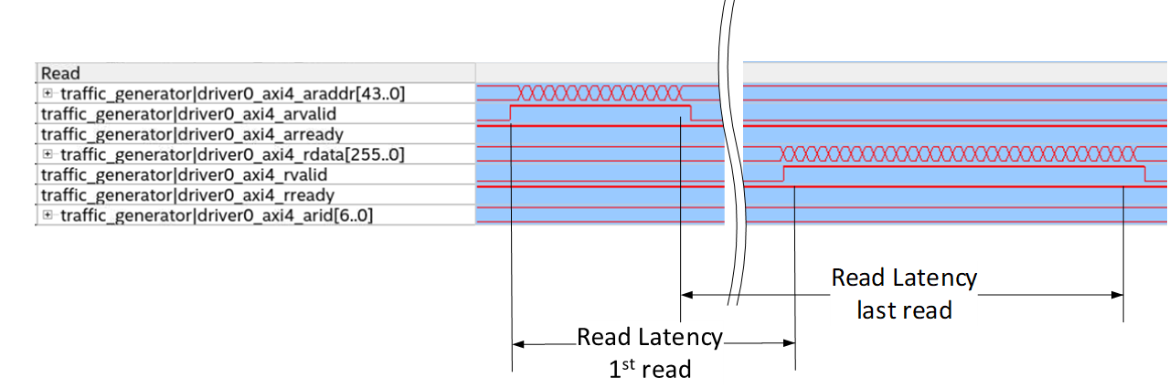
The AXI transactions are pipelined, and many transactions can issue before the first response returns. Therefore, to measure latency correctly, you must implement a mechanism to determine which response corresponds to each request. The easiest method is to begin measuring at the first transaction, and match requests to responses by following the sequential order of responses for each AxID. There is no general method of measuring latency from a Signal Tap capture in the middle of an ongoing set of transactions. To match transactions requests to their responses, you must use the application-specific identifying characteristics, such as observing what data transfers.