Visible to Intel only — GUID: ckj1482303472625
Ixiasoft
Advantages of Partial Reconfiguration
Scope of This Document
Prerequisites for Using This Document
Partial Reconfiguration Tools and Methods
Arria 10 SoC Partial Reconfiguration Workflow
Partial Reconfiguration Limitations
Creating the PR Example Design
Generating the Example Software Image
Loading Partial Reconfiguration Designs Using Linux
Important Partial Reconfiguration Terminology
Revision History
Qsys Partial Reconfiguration Freeze Logic
Importing the GHRD Project
Add a Partial Reconfiguration Region to the GHRD
Building the Base Revision with the Reconfigurable Design Partition
Synthesizing an Alternate Persona
Implementing the Alternate Persona
Generating the RBF FPGA Image Files
Design Handoff to Software Developer
Visible to Intel only — GUID: ckj1482303472625
Ixiasoft
Creating the Partial Reconfiguration Design
This design contains all the logic for the default persona of the PR region that is added to the GHRD Qsys design later.
The PR region contains three components for this example:
- An Avalon-MM pipeline bridge, to split the bus address space for the other two components and isolate bus timing.
- Memory to access from the Avalon-MM bus.
- A system ID peripheral component. This component is accessible from the Avalon-MM bus and provides a static version number that can be read by software to determine what logic has been loaded into the PR region.
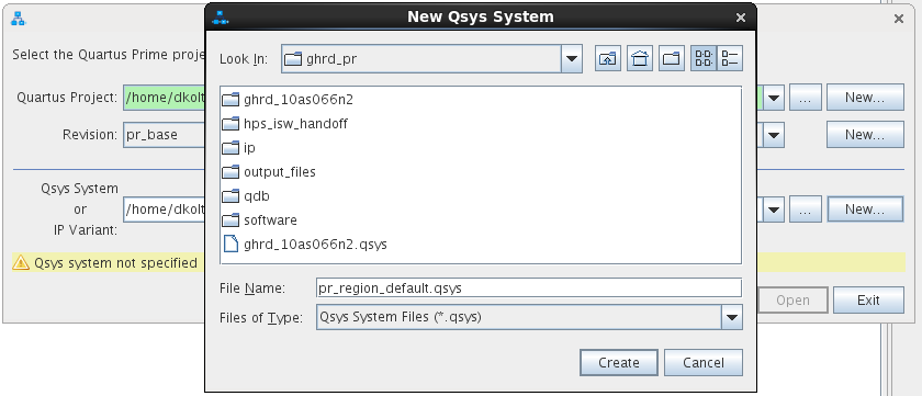
- Open the Qsys Pro tool again and create a new system design named pr_region_default.qsys.
Figure 8. Creating the Qsys Project for the Partial Reconfiguration Design
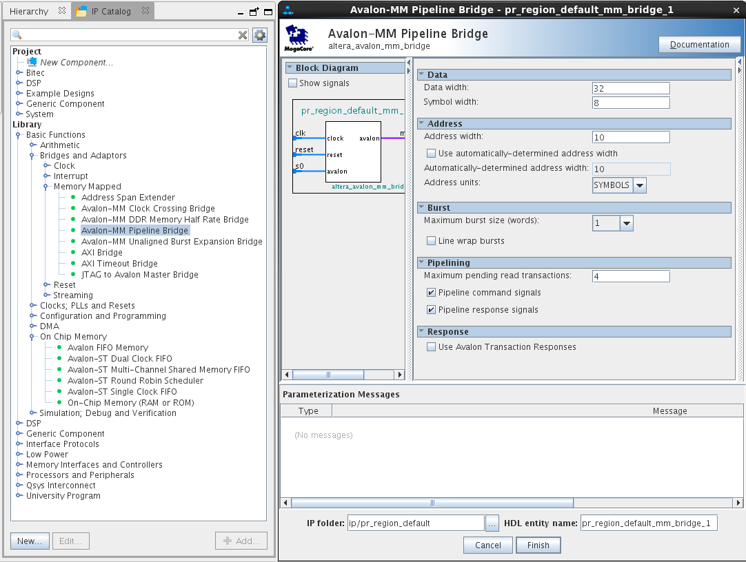
- Add an Avalon-MM pipeline bridge to the design as shown below.
Figure 9. Adding the Avalon-MM Pipeline Bridge
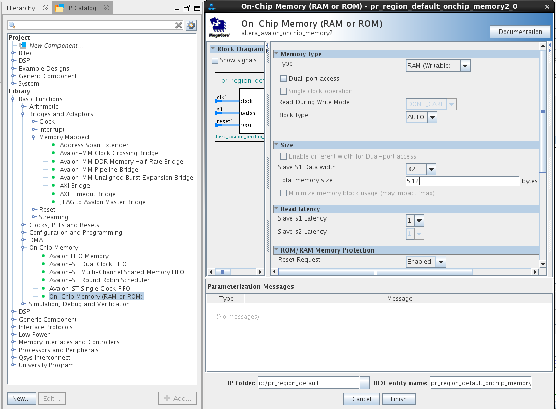
- Add a 512 byte, 32-bit wide on-chip memory as shown below.
Note: Scroll down and turn off the Initialize Memory Content option. Otherwise, Qsys will require an initialization data file.Figure 10. Adding On-Chip Memory
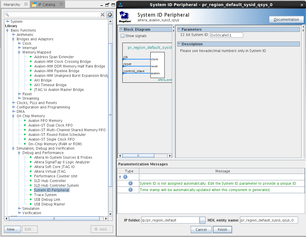
- Add a system ID peripheral component as shown below. Set the 32-bit System ID field to something unique.
Figure 11. Adding the System ID
- Hook up the Qsys system as shown below by clicking on the appropriate connection bubbles.
Figure 12. Configuring the System Connections
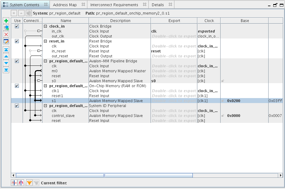
- Export the Avalon-MM pipeline bridge slave port and give it an exported name of s0.
- Change the on-chip base address to 0x0200 and leave the system ID peripheral base address at 0x0000.
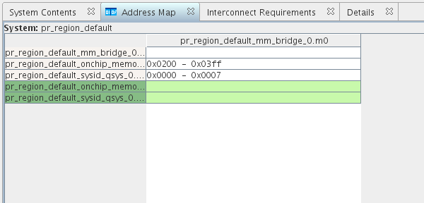
- Confirm the address map is correct by reviewing the configuration in the Address Map tab. It should look like the configuration shown below.
Figure 13. Address Map Example
- Save the design and click Finish.