Visible to Intel only — GUID: jlg1482303491810
Ixiasoft
Advantages of Partial Reconfiguration
Scope of This Document
Prerequisites for Using This Document
Partial Reconfiguration Tools and Methods
Arria 10 SoC Partial Reconfiguration Workflow
Partial Reconfiguration Limitations
Creating the PR Example Design
Generating the Example Software Image
Loading Partial Reconfiguration Designs Using Linux
Important Partial Reconfiguration Terminology
Revision History
Qsys Partial Reconfiguration Freeze Logic
Importing the GHRD Project
Add a Partial Reconfiguration Region to the GHRD
Building the Base Revision with the Reconfigurable Design Partition
Synthesizing an Alternate Persona
Implementing the Alternate Persona
Generating the RBF FPGA Image Files
Design Handoff to Software Developer
Visible to Intel only — GUID: jlg1482303491810
Ixiasoft
Adding the PR Region
- Reopen the GHRD Qsys system design.
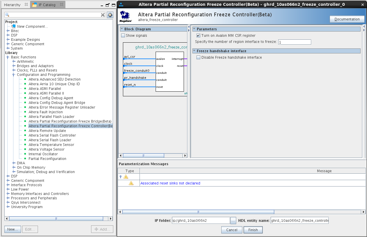
- Add an Intel® partial reconfiguration freeze controller.
Figure 14. Adding the Partial Reconfiguration Freeze Controller
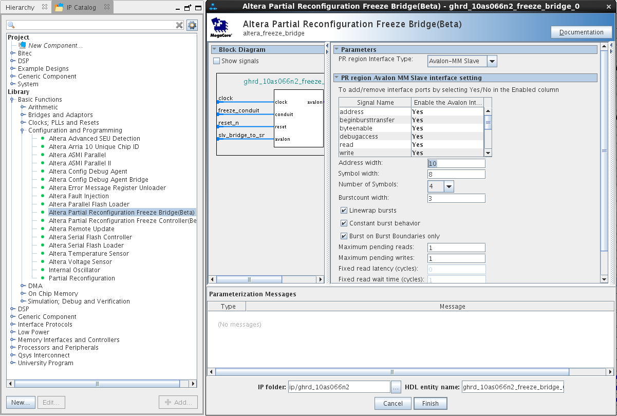
- Add an Intel partial reconfiguration freeze bridge.
Figure 15. Adding the Partial Reconfiguration Freeze Bridge
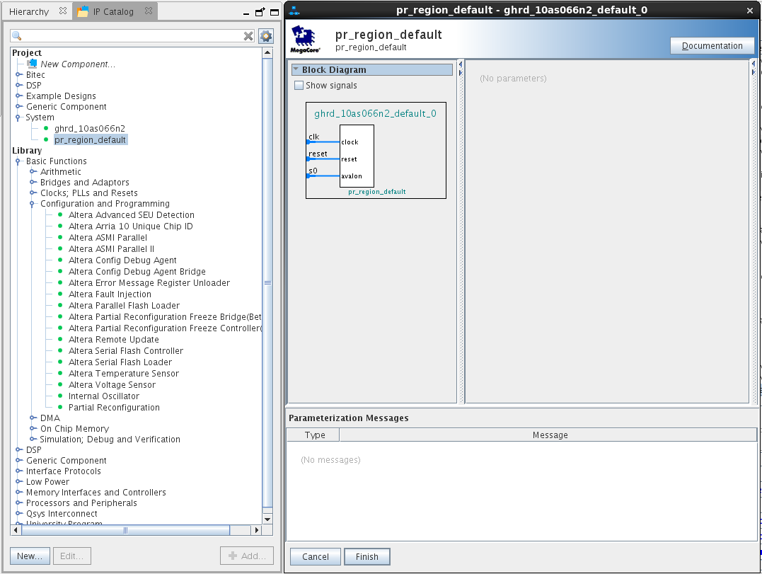
- Add the PR Region Default Qsys system to the design as shown below. The previously created pr_region_default Qsys system is in the System category of the IP catalog.
Figure 16. Adding the PR Region Default Qsys System
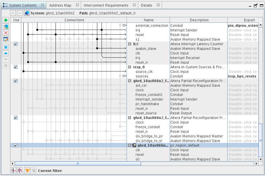
- Confirm the additions to the GHRD Qsys system design by comparing the System Contents tab shown below.
Figure 17. Resulting Design
- Connect the new components as shown below. Export the pr_handshake conduit interface of the Intel® partial reconfiguration freeze controller to the top level with the name pr_handshake.
Note: The freeze controller's interrupt_sender output signal is disconnected, because the Linux driver polls a status bit rather than using an interrupt. You might see a Qsys warning message, which you can ignore.Figure 18. PR Region Connections
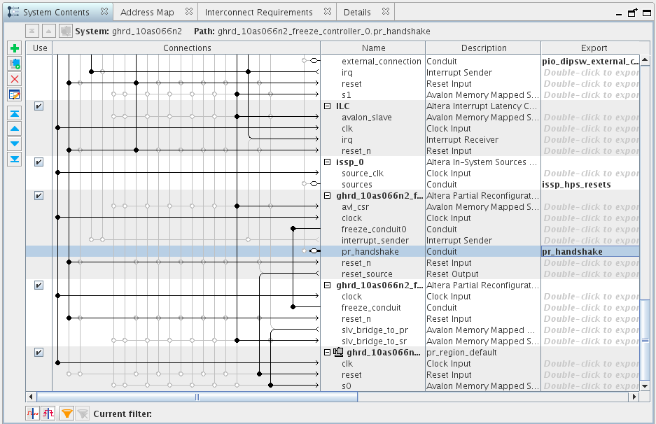
- Edit the system address memory map using the Address Map tab as shown below.
Note: Pay attention to the freeze controller and freeze bridge base addresses. These are crucial parts of the handoff information provided to the host software designer.Figure 19. System Address Memory Map
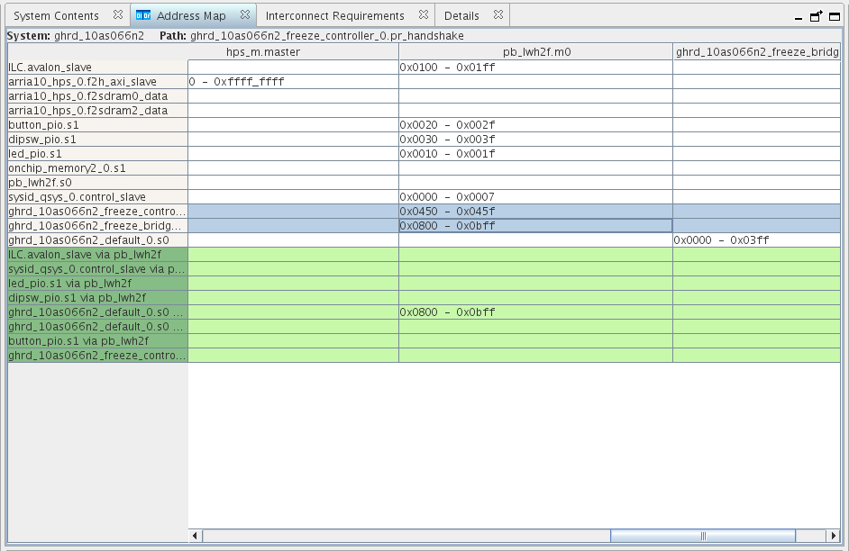
- Force the pb_lwh2f address width to automatically readjust by unchecking, and then re-checking the Use automatically-determined address width box in the component dialog. Qsys sets the address width to 12 bits.
Figure 20. Pipeline Bridge Data Width
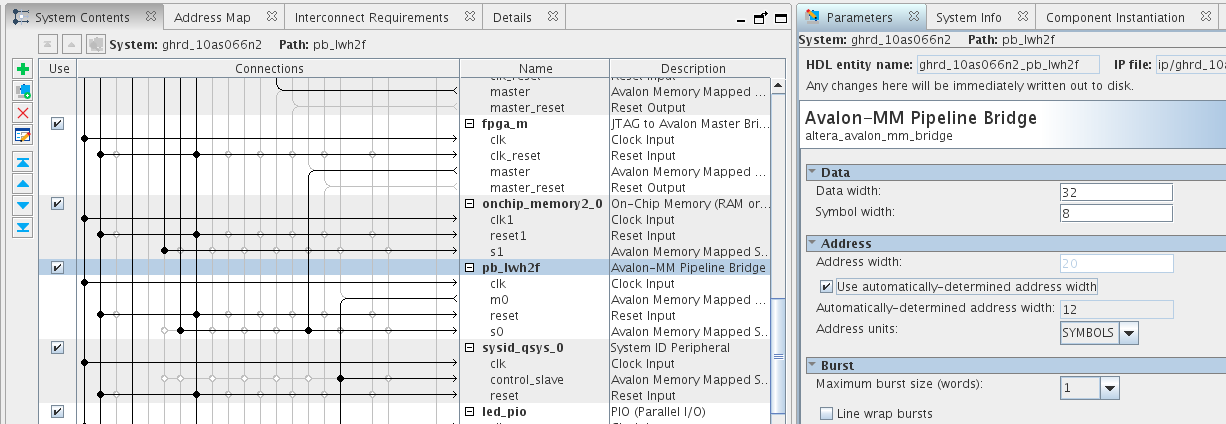
- Adjust the address map to eliminate any overlaps or alignment issues.
- Click Generate RTL to create the new system.
- Click Finish.