Intel® Integrated Performance Primitives (Intel® IPP) Developer Guide and Reference
A newer version of this document is available. Customers should click here to go to the newest version.
Canny Edge Detector
This subsection describes a classic edge detector proposed by J.Canny, see [Canny86 ]. The detector uses a grayscale image as an input and outputs a black-and-white image, where non-zero pixels mark detected edges. The algorithm consists of three stages described below.
Stage 1: Differentiation
The image data is differentiated in x and y directions. From the computed x and y gradient components, Canny edge detector functions calculate the magnitude and angle of the gradient vector.
The ippiSobel functions perform the first stage and Canny edge detector functions use their output.
Stage 2: Non-Maximum Suppression
With the rate of intensity change found at each point in the image, edges must be placed at the points of maximum values of gradient magnitude. It is preferable to suppress non-maximum points that are perpendicular to the edge direction, rather than parallel to the edge direction, as the edge is strong along an extended contour.
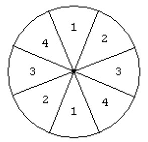
The algorithm starts off with sorting the direction of gradient to one of four sectors shown in the figure below.

The algorithm passes a 3x3 neighborhood across the magnitude array. At each point, the center element of the neighborhood is compared with its two neighbors along the line of the gradient given by the sector value. If the central value is not greater than the neighbors, it is suppressed.
Stage 3: Edge Thresholding
The Canny operator uses the so-called “hysteresis” thresholding. Most thresholders use a single threshold limit, which means that if the edge values fluctuate above and below this value, the line appears broken. This phenomenon is commonly referred to as “streaking”. Hysteresis counters streaking by setting an upper and lower edge value limit. Considering a line segment, if a value lies above the upper threshold limit, it is immediately accepted. If the value lies below the low threshold, it is rejected. Points which lie between the two limits are accepted if they are connected to pixels which are also accepted. The likelihood of streaking is small, since the line segment points must fluctuate above the upper limit and below the lower limit for streaking to occur.
J.Canny recommends the ratio of high to low limit be in the range two or three to one, based on predicted signal-to-noise ratios.
Example shows how to use the Intel IPP functions for the Canny edge detector.
- CannyBorderGetSize
Calculates the size of the temporary buffer for the ippiCannyBorder function. - CannyBorder
Implements Canny algorithm for edge detection. - CannyGetSize
Calculates size of temporary buffer for the ippiCanny function. - Canny
Implements Canny algorithm for edge detection. - EigenValsVecsGetBufferSize
Calculates size of temporary buffer for the function ippiEigenValsVecs. - EigenValsVecsBorder
Calculates eigen values and eigen vectors of image blocks for corner detection. - EigenValsVecs
Calculates eigen values and eigen vectors of image blocks for corner detection. - MinEigenValGetBufferSize
Calculates size of temporary buffer for the function ippiMinEigenVal. - MinEigenValBorder
Calculates the minimal eigen value of image blocks for corner detection. - MinEigenVal
Calculates the minimal eigen value of image blocks for corner detection.