Visible to Intel only — GUID: oyz1687889346952
Ixiasoft
Visible to Intel only — GUID: oyz1687889346952
Ixiasoft
3.1. Board Decoupling Capacitors Guide
In addition to on-package decoupling (OPD) (as land-side capacitor (LSC) and die-side capacitor (DSC)), the Agilex™ 5 device family also offers a bottom side and periphery capacitors (refer to the Agilex™ 5 FPGA Packages Board-Level Decoupling Capacitors Summary section, the bottom side capacitors for each power rail) can be added into the Agilex™ 5 E-Series Group B modular development kit (SOM) as shown in the following figures.
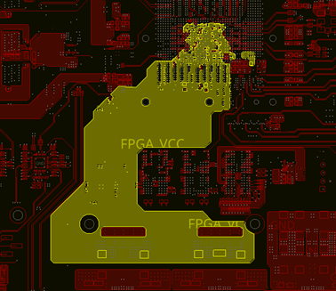
The following figures are examples of a decoupling capacitor placed on the bottom side and periphery for a PCB designed for the Agilex™ 5 E-Series Group B modular development kit (SOM) without socket and the use of PTH via.
Considering the Variable Pitch Ball Grid Array (VPBGA) mapping, Altera recommends you include power flood on the bottom layer of the board for VCCL. The following example is a good design practice that has shown to reduce the loop inductance due to a shorter path to FPGA fabric and more effective decoupling solution.
