Visible to Intel only — GUID: xir1529450502879
Ixiasoft
5.3.4. The EPCQ Tab
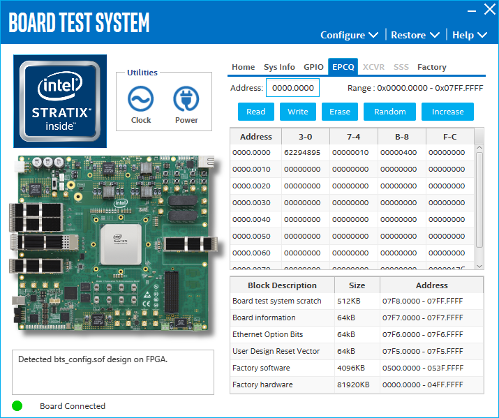
The EPCQ tab allows you to read and write flash memory on your board.

The following sections describe the controls on the EPCQ tab.
Read
Write
The Write control writes the flash memory on your board. To update the flash memory contents, change values in the table and click Write. The application writes the new values to flash memory and then reads the values back to guarantee that the graphical display accurately reflects the memory contents.
Erase
When erasing flash memory contents should read FFFFFFFF, which is limited to a scratch page in the upper 512K block.
Increase
Start an increase data pattern to test flash memory.
Random
Starts a random data pattern to test flash memory.
Flash Memory Map
Displays the flash memory map for the Intel® Stratix® 10 TX transceiver signal integrity development board.