Visible to Intel only — GUID: zyg1619090945742
Ixiasoft
1. About the Video and Vision Processing Suite
2. Getting Started with the Video and Vision Processing IPs
3. Video and Vision Processing IPs Functional Description
4. Video and Vision Processing IP Interfaces
5. Video and Vision Processing IP Registers
6. Video and Vision Processing IPs Software Programming Model
7. Protocol Converter Intel® FPGA IP
8. 1D LUT Intel® FPGA IP
9. 3D LUT Intel® FPGA IP
10. Adaptive Noise Reduction Intel® FPGA IP
11. Advanced Test Pattern Generator Intel® FPGA IP
12. AXI-Stream Broadcaster Intel® FPGA IP
13. Bits per Color Sample Adapter Intel® FPGA IP
14. Black Level Correction Intel® FPGA IP
15. Black Level Statistics Intel® FPGA IP
16. Chroma Key Intel® FPGA IP
17. Chroma Resampler Intel® FPGA IP
18. Clipper Intel® FPGA IP
19. Clocked Video Input Intel® FPGA IP
20. Clocked Video to Full-Raster Converter Intel® FPGA IP
21. Clocked Video Output Intel® FPGA IP
22. Color Plane Manager Intel® FPGA IP
23. Color Space Converter Intel® FPGA IP
24. Defective Pixel Correction Intel® FPGA IP
25. Deinterlacer Intel® FPGA IP
26. Demosaic Intel® FPGA IP
27. FIR Filter Intel® FPGA IP
28. Frame Cleaner Intel® FPGA IP
29. Full-Raster to Clocked Video Converter Intel® FPGA IP
30. Full-Raster to Streaming Converter Intel® FPGA IP
31. Genlock Controller Intel® FPGA IP
32. Generic Crosspoint Intel® FPGA IP
33. Genlock Signal Router Intel® FPGA IP
34. Guard Bands Intel® FPGA IP
35. Histogram Statistics Intel® FPGA IP
36. Interlacer Intel® FPGA IP
37. Mixer Intel® FPGA IP
38. Pixels in Parallel Converter Intel® FPGA IP
39. Scaler Intel® FPGA IP
40. Stream Cleaner Intel® FPGA IP
41. Switch Intel® FPGA IP
42. Text Box Intel® FPGA IP
43. Tone Mapping Operator Intel® FPGA IP
44. Test Pattern Generator Intel® FPGA IP
45. Unsharp Mask Intel® FPGA IP
46. Video and Vision Monitor Intel FPGA IP
47. Video Frame Buffer Intel® FPGA IP
48. Video Frame Reader Intel FPGA IP
49. Video Frame Writer Intel FPGA IP
50. Video Streaming FIFO Intel® FPGA IP
51. Video Timing Generator Intel® FPGA IP
52. Vignette Correction Intel® FPGA IP
53. Warp Intel® FPGA IP
54. White Balance Correction Intel® FPGA IP
55. White Balance Statistics Intel® FPGA IP
56. Design Security
57. Document Revision History for Video and Vision Processing Suite User Guide
31.4.1. Achieving Genlock Controller Free Running (for Initialization or from Lock to Reference Clock N)
31.4.2. Locking to Reference Clock N (from Genlock Controller IP free running)
31.4.3. Setting the VCXO hold over
31.4.4. Restarting the Genlock Controller IP
31.4.5. Locking to Reference Clock N New (from Locking to Reference Clock N Old)
31.4.6. Changing to Reference Clock or VCXO Base Frequencies (switch between p50 and p59.94 video formats and vice-versa)
31.4.7. Disturbing a Reference Clock (a cable pull)
Visible to Intel only — GUID: zyg1619090945742
Ixiasoft
43.1. About the Tone Mapping Operator IP
The tone mapping operator (TMO) Intel FPGA IP dynamically adapts the processing of an image based on a regional (tile-based) approach. It improves the visibility of latent image detail and enhances the overall viewing experience.
You can configure the required number of bits per symbol and pixels in parallel. Typical applications include:
- Medical imaging
- Machine vision
- Video conferencing
- Surveillance
- Automotive imaging
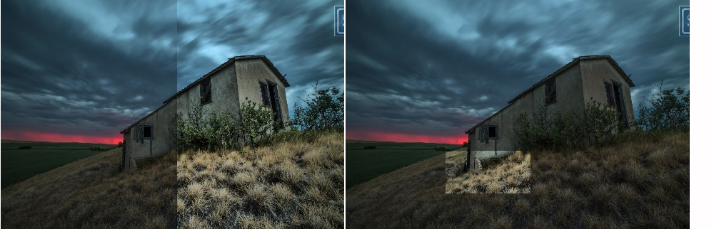
Figure 117. Example of processing a real-life image using the TMO IPThe figure shows example results obtained after applying the TMO IP dataflow on a real-life image: left is the original image; right is the output image after TMO IP processing.

You provide and receive video data to the TMO IP in RGB format via the AXI4-Stream compatible Intel FPGA video streaming interfaces. The IP determines the size of the video busses from the number of pixels processed per clock cycle, the color bit depth, and the number of component streams parameters. The number of video component streams is fixed at 3. The IP supports:
- Component bit depths of 8, 10 and 12-bit.
- Pixels per clock of 1, 2 and 4.
You control the strength of the contrast enhancement for the output images provided by the TMO IP via an Avalon memory-mapped control interface. The data bus for the control interface is set to 32-bit to interface with an embedded CPU. During operation, you can configure the TMO IP using a software driver that controls all the IP parameters via a set of software APIs.
The TMO IP allows four modes of operations:
- Passthrough
- Contrast-enhancement
- Horizontal and vertical slider
- Region of interest
The Example of processing a real-life image using the TMO IP figure shows passthrough and contrast enhancement.
Region of interest allows you to define a specific window within the active picture, so that the contrast enhancement is only applied in that specific part of the output image.
Figure 118. Examples of horizontal slider and region of interest
The TMO IP supports RGB sampling. The sampling method at the output is always the same as the input. You must provide details of the current standard video resolution via the CPU control interface to ensure correct behavior. the IP only supports 4:4:4 progressive sampling. You should perform any deinterlacing and chroma up or down sampling externally to the TMO IP.
The IP only supports lite variants. For more information about full and lite variants, refer to the Intel FPGA Streaming Video Protocol Specification
Related Information