1.5. Duty Cycle Distortion Calibration
Duty Cycle Distortion (DCD) calibration is used to calibrate the TX duty cycle to compensate for the skew introduced by different clock networks.
You must turn on the DCD calibration IP when you switch from 2500 Mbps to 5000 Mbps, because TX PLL switching causes a different clock network to be used.
Enable the DCD calibration IP for Arria V and Cyclone V devices if either of the following conditions is applicable:
- Data rate is ≥ 4915.2 Mbps
- Clock network switching (TX PLL switching) and the data rate is ≥ 4915.2 Mbps
The DCD calibration features and options are summarized in the following table. Refer to the usage condition to enable the DCD Calibration IP.
| Transceiver Calibration Function |
Option |
Description |
Usage Condition |
|---|---|---|---|
| Enable duty cycle calibration |
Enabled |
Use DCD calibration IP either during power up or user mode |
|
| Disabled |
Disabled DCD calibration features |
Data rate < 4915.2 Mbps |
|
| Calibrate duty cycle during power up |
Enabled |
DCD calibration IP process at power up mode and during user mode (manual DCD calibration) |
Data rate ≥ 4915.2 Mbps |
| Disabled |
DCD calibration IP will not start at power up mode, but can still be triggered during user mode if the Enable duty cycle calibration option is enabled |
|
|
| Create optional calibration status ports |
N/A |
tx_cal_busy , rx_cal_busy , cal_busy_in ports exposed |
tx_cal_busy should be connected to cal_busy_in port if you are using more than one Reconfiguration Controller per side of the device |
Note: Do not enable DCD calibration for applications running at < 4915.2 Mbps.
The following table lists the data rate usage conditions and when to enable the power up and manual DCD calibration IP.
| Data Rate (Mbps) Usage Conditions | DCD Calibration | |||
|---|---|---|---|---|
| Case | From | To | Power Up | Manual |
| Data Rate Switch | ||||
| 1 | < 4915.2 | < 4915.2 | x | x |
| 2 | < 4915.2 | ≥ 4915.2 | x | Enabled |
| 3 | ≥ 4915.2 | < 4915.2 | Enabled | x |
| 4 | ≥ 4915.2 | ≥ 4915.2 | N/A | N/A |
| Example 1 | 6144 | 9830.4 | Enabled | Enabled |
| Example 2 | 9830.4 | 6144 | Enabled | x |
| Clock Network Switch (TX PLL Switching) | ||||
| 1 | < 4915.2 | < 4915.2 | x | x |
| 2 | < 4915.2 | ≥ 4915.2 | x | Enabled |
| 3 | ≥ 4915.2 | < 4915.2 | Enabled | x |
| 4 | ≥ 4915.2 | ≥ 4915.2 | Enabled | Enabled |
Note: If you have channels that need to enable DCD calibration IP from both the left and right sides of the device, you must use one transceiver reconfiguration controller per side of the device. This applies to both power-up and manual DCD mode.
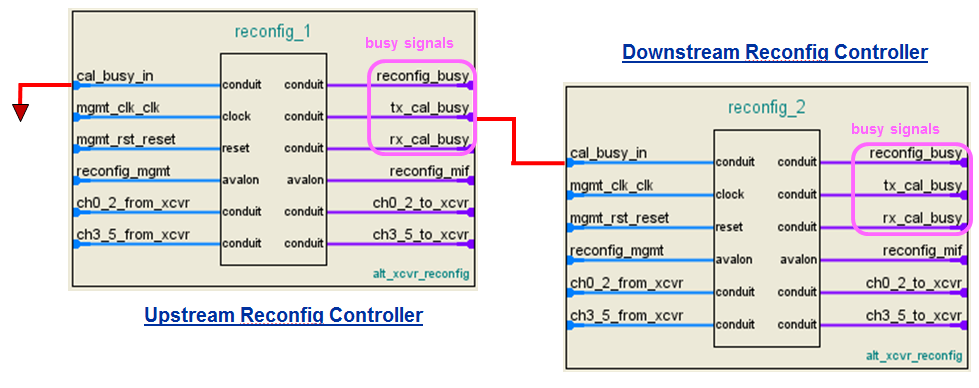
If your design is using more than one Reconfiguration Controller (per side of the device) and the data channels are running ≥ 4915.2 Mbps, you must chain the Reconfiguration Controller. The following figure shows the chaining method. The chaining is required from the first Reconfiguration Controller until the last Reconfiguration Controller (per side of the device), as long as the DCD calibration IP is enabled.
The purpose of chaining the Reconfiguration Controller is to allow the DCD calibration process to execute sequentially. For example, in the following figure, by chaining the tx_cal_busy signal in the upstream Reconfiguration Controller to the cal_busy_in port of the downstream Reconfiguration Controller, the DCD is calibrated for the transceiver channels connected to the upstream controller before the transceiver channels connected to the downstream controller.
The cal_busy_in port will reset the downstream Reconfiguration Controller when the upstream Reconfiguration Controller is busy with the DCD calibration. The cal_busy_in port of the upstream Reconfiguration Controller is connected to ground. The tx_cal_busy port of the downstream Reconfiguration Controller can be left unconnected.
Note: If you are using only one Reconfiguration Controller with DCD calibration enabled, the cal_busy_in port must be tied to ground.
This process is handled by the Reconfiguration Controller internally. You only need to connect the ports as described for proper functionality.
Figure 10. Chaining the Reconfiguration Controller
As this design example demonstrates, the Reconfiguration Controller provides an easy and efficient method to dynamically change the Arria V GX Native PHY IP's settings, including TX PLL switching, VOD setting updates, and triggering the DCD calibration process during user mode.