4.3.3. Upgrading IP Cores
When updating a design from an older version of the Quartus® Prime software, the Quartus® Prime Pro Edition software displays an IP upgrade required sign if the IP cores included in the design need upgrade.
Follow these steps to upgrade the IP core:
- Click Launch IP Upgrade Tool.
Figure 13. Launch IP Upgrade Tool Bar in the Quartus® Prime Pro Edition Software

In the Upgrade IP Components dialog, the Auto Upgrade button is greyed out, which means that you must upgrade the Platform Designer system manually.
Figure 14. Upgrade IP Components Dialog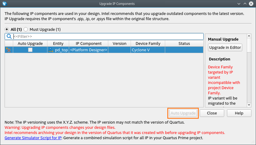 Note: You have two options for upgrading IPs. Depending on the severity of the IP upgrade needed, you can perform an automatic upgrade in the Upgrade IP Components dialog or a manual upgrade using the Platform Designer. Elaborations are presented if a manual upgrade is needed.
 - Click the Upgrade in Editor button to perform a manual upgrade.
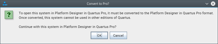
You are prompted to convert the system to Pro format, with a warning that it cannot be used in other editions of the Quartus® Prime software.
- Click OK.
Figure 15. Warning Message
 Note: Click to save a copy of your original project before making modifications for migration.
Observe the conversion results once the Platform Designer in Quartus Pro Conversion Results dialog appears. Updated IP Variants are automatically added to the Quartus® Prime project.
Figure 16. Platform Designer in Quartus Pro Conversion Results Dialog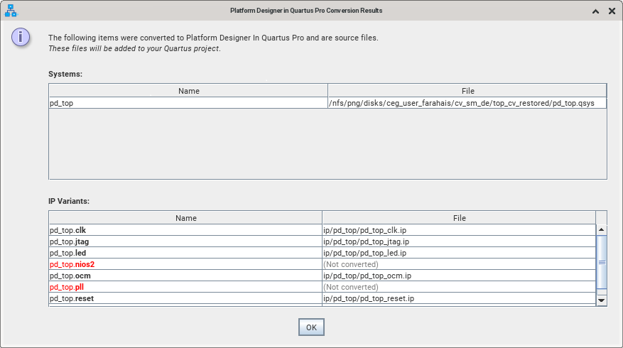
- Click OK.
Note: There may be a dialog displaying ‘What’s New!’ in the Platform Designer. You can explore the information about new features and close the window.
- Close the Open System Completed dialog.
The Platform Designer GUI shows that all IP cores have been automatically upgraded to the latest version. To further confirm this, click . No IP cores are listed, as everything has been updated to the latest version.
Figure 17. Upgrade IP Cores Dialog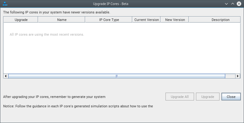
- Upgrade IP Cores manually in the Platform Designer as shown in the following sections.
Upgrading PLL Intel® FPGA IP
In the Platform Designer System View, observe that the pll IP core is highlighted in red.
Figure 18. pll IP core in the System View
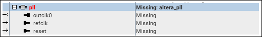
The IP component is missing its details. This is because the PLL Intel® FPGA IP used in the Cyclone® V design is supported only by certain device families in the Quartus® Prime Standard Edition. This IP core is unavailable in the Quartus® Prime Pro Edition edition. In the right-hand Parameters tab, the IP is shown as a Missing Module.
Figure 19. Missing Module Dialog
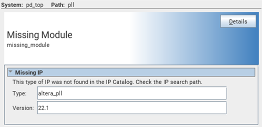
The closest equivalent for the IP core in the Quartus® Prime Pro Edition is the IOPLL Intel® FPGA IP. For other IP cores showing Missing Module, refer to IP Comparison Between Cyclone V and Agilex 5 Devices for the IP core replacements in the Quartus® Prime Pro Edition software. You can also create a custom IP using the Quartus® Prime Standard Edition User Guide: Platform Designer .
To replace the missing module with the IOPLL Intel® FPGA IP, perform the following steps:
- Remove the component from the system by right-clicking on pll and click Remove in its context-sensitive menu.
- In the tab, search iopll.
Figure 20. Searching iopll in the IP Catalog
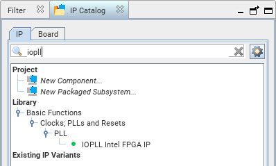
- Double-click the IP core under to instantiate the IP. The IOPLL Intel® FPGA IP dialog appears.
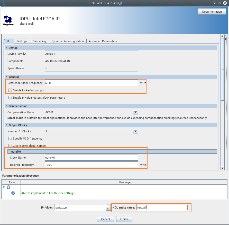
- Parametrize the IP.
- Set the Reference Clock Frequency to 50 MHz.
- Uncheck the Enable locked output port option.
- Set outclk0’s Desired Frequency to 125 MHz.
- Leave the remaining fields with their default values.
- In the HDL entity name field, name the IP component as new_pll.
Figure 21. Parameterization of the IOPLL Intel® FPGA IP
- Click Finish.
- Shift the IP to be under reset IP by selecting the component and clicking the Move Up button.
Figure 22. new_pll IP in the System View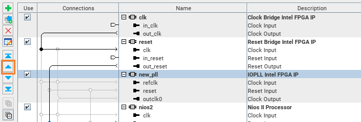
Nios® II Processor
Altera® has discontinued the support for the Nios® II Processor in March 2024 (see PDN 2312). You must upgrade any Nios® II usage to the Nios® V processor variants.
Figure 23. Missing Nios® V Module in the Parameters View
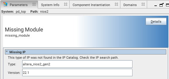
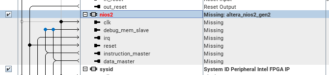
Figure 24. Missing Nios® V Module in the System View
Replace the Nios® II Processor in this design with the Nios® V/m Microcontroller Intel® FPGA IP. For more information about the Nios® V processor, refer to the Nios® V Embedded Processor Design Handbook .
Remove the IP core and replace it using the following steps:
- Remove the nios2 component by right-clicking on it and selecting Remove in its context-sensitive menu.
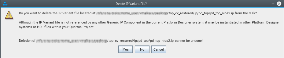
- Click Yes for the delete IP variant file warning message.
Figure 25. Delete IP Variant File Warning Message
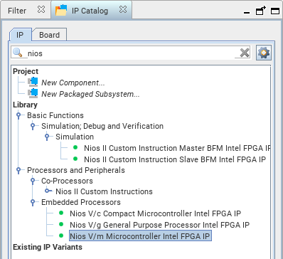
- From the IP Catalog, search nios.
- Double-click Nios® V/m Microcontroller Intel® FPGA IP under .
Figure 26. Searching nios in the IP Catalog
- Instantiate the IP using the default configurations.
- Rename the HDL entity name to niosv.
Figure 27. Parameterization of the Nios® V/m Microcontroller Intel® FPGA IP
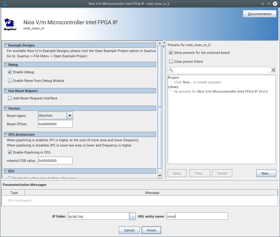
- Click Finish.
- Using the Move Up button, move niosv to be under the new_pll component.
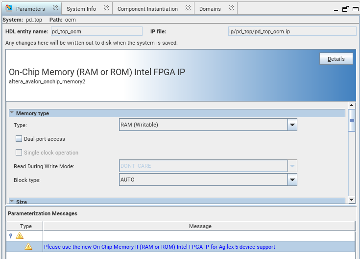
On-Chip Memory (RAM or ROM) Intel® FPGA IP
When you select the ocm IP component (On-Chip Memory (RAM or ROM) Intel® FPGA IP) in the System View, you can observe warning messages in the pane, which suggests using the On-Chip Memory (RAM or ROM) II Intel® FPGA IP as a replacement because the previous IP is not supported by Agilex™ 5 devices.
Figure 28. Parameterization of the On-Chip Memory (RAM or ROM) Intel® FPGA IP
To remove the IP core and replace it, perform these steps:
- Remove the component by right-clicking on the ocm IP component and choosing Remove from its context-sensitive menu.
- Click Yes to the warning message about the IP deletion and that the IP variant file deletions cannot be undone.
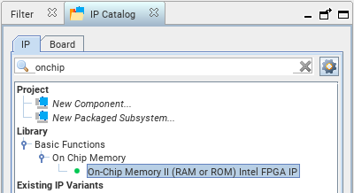
- From the IP Catalog, search onchip.
- Double-click On-Chip Memory II (RAM or ROM) Intel® FPGA IP under .
Figure 29. Searching onchip in the IP Catalog
- Parametrize the IP.
- Set Total Memory Size to 64000 bytes.
- Rename the HDL entity name field to new_ocm.
- Click Finish.
Agilex Reset Release Intel® FPGA IP
Intel® requires that you use the Reset Release Intel® FPGA IP to hold your design in reset until the configuration is complete. For more information about this IP core, refer to the Device Configuration User Guide: Agilex™ 5 FPGAs and SoCs .
To add the IP core, follow these steps:
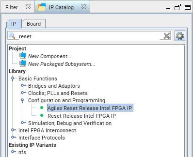
- From the IP Catalog, search reset.
- Double-click Agilex Reset Release Intel® FPGA IP under to instantiate the IP.
Figure 30. Searching reset in the IP Catalog
- Set Type of reset output port to Reset Interface.
- Rename the HDL entity name to resetrelease.
- Click Finish.