Visible to Intel only — GUID: muv1702491647321
Ixiasoft
2.1. Device Footprint
2.2. Power Management
2.3. Configuration
2.4. Design Security Differences
2.5. Logic Elements and Embedded Memory
2.6. PLL and Clock Network
2.7. Digital Signal Processing (DSP)
2.8. I/O Interfaces
2.9. LVDS SERDES Interface
2.10. Sensor Monitoring System
2.11. MIPI D-PHY Interface
2.12. External Memory Interface (EMIF)
2.13. Hard Processor System (HPS)
2.14. Transceiver and Serial Protocols
2.15. PCIe Interface
2.16. Ethernet Interface
2.3.1. General Configuration Pin and Sequences
2.3.2. Device Configuration and the Secure Device Manager (SDM)
2.3.3. Active Serial (AS) Configuration
2.3.4. Avalon® -ST Configuration
2.3.5. JTAG Configuration
2.3.6. Configuration via Protocol (CvP)
2.3.7. QSPI Flash Access and Remote System Upgrade Feature
2.3.8. SEU Features
2.3.9. Configuration File Format Differences
Visible to Intel only — GUID: muv1702491647321
Ixiasoft
4.3.4. Establishing Connections
After parameterizing the IPs, you might observe several messages, errors, and warnings in the System Messages tab. You can resolve these messages by establishing proper connections.
- Establish proper connections by right-clicking on the component, selecting Connections, and choosing options based on the following table:
From To clk clk.out_clk reset.clk clk.out_clk new_pll.refclk reset reset.out_reset new_pll.reset reset.out_reset niosv.reset reset.out_reset new_ocm.reset1 new_pll new_pll.outclk0 niosv.clk new_pll.outclk0 sysid.clk new_pll.outclk0 new_ocm.clk1 new_pll.outclk0 led.clk new_pll.outclk0 jtag.clk niosv niosv.instruction_manager new_ocm.s1 niosv.data_manager new_ocm.s1 niosv.data_manager sysid.control_slave niosv.data_manager led.s1 niosv.data_manager jtag.avalon_jtag_slave niosv.platform_irq_rx jtag.irq resetrelease resetrelease.ninit_done niosv.reset - Sync all system information by clicking Sync System Infos.
- For niosv, in the Parameters > Vectors tab, set Reset Agent to new_ocm.s1. This can only be done after making the connections.
- Remove the overlapping address error by clicking System > Assign Base Addresses. System Messages must be clear of any messages by this point.
- Click File > Save.
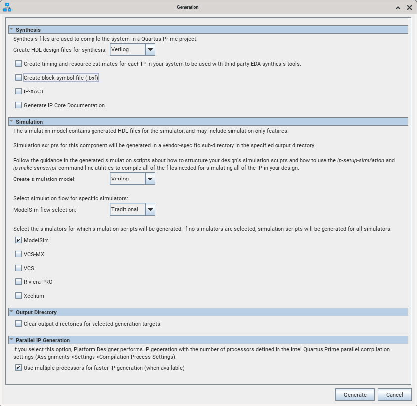
- Click Generate > Generate HDL.
- Under Synthesis, uncheck Create block symbol file (.bsf) and Generate IP core Documentation options.
- Under Simulation, select Verilog for Create simulation model. Traditional for ModelSim flow selection and check ModelSim.
Figure 31. Generation Dialog
- Click Generate. Once generation is complete, click Close.