Visible to Intel only — GUID: vwf1686164996264
Ixiasoft
1. Overview
2. Getting Started
3. Development Kit Setup
4. Board Test System
5. Development Kit Hardware and Configuration
6. Custom Projects for the Development Kit
7. Document Revision History for the Agilex™ 7 FPGA M-Series HBM2e Development Kit User Guide
A. Development Kit Components
B. Additional Information
Visible to Intel only — GUID: vwf1686164996264
Ixiasoft
4.4. Monitoring On-Board Power Regulator through Power Monitor GUI
The Power Monitor GUI reports most power rails’ voltage, current, and power information on the board. It also collects temperature from FPGA die, power modules, and diodes assembled on PCB.
The Power Monitor GUI communicates with System MAX® 10 through a 10-pin JTAG header J7 or USB port J1. System MAX® 10 monitors and controls power regulator, temperature/voltage/current sensing chips through a 2-wire I2C bus.
The instructions to run Power Monitor GUI are stated in the Running the BTS GUI section. It can also be started with the BTS GUI icon Power.
Note: You cannot run the stand-alone Power Monitor GUI when the BTS or the Clock Controller GUI is running at the same time.
Figure 24. Power Monitor GUI — The Power Tab
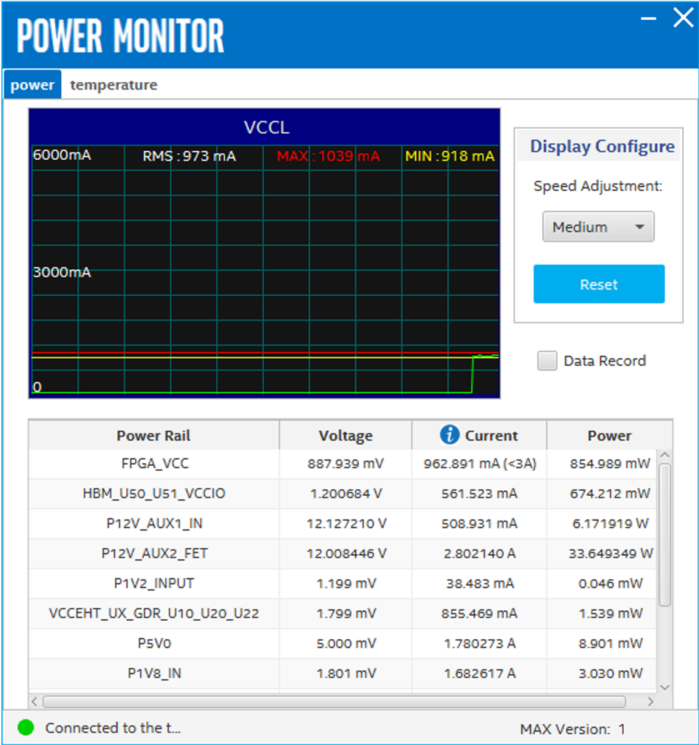
The following sections describe the details of the Power Monitor GUI.
Display Configure
- Speed Adjustment: Adjusts the update rate of the current curve.
- Reset: Regenerates the graph.
Data Record
When the box is checked, the telemetry data of the selected power rail can be recorded. It saves the data into a .csv file in the log directory.
Figure 25. Power Monitor GUI—The Temperature Tab
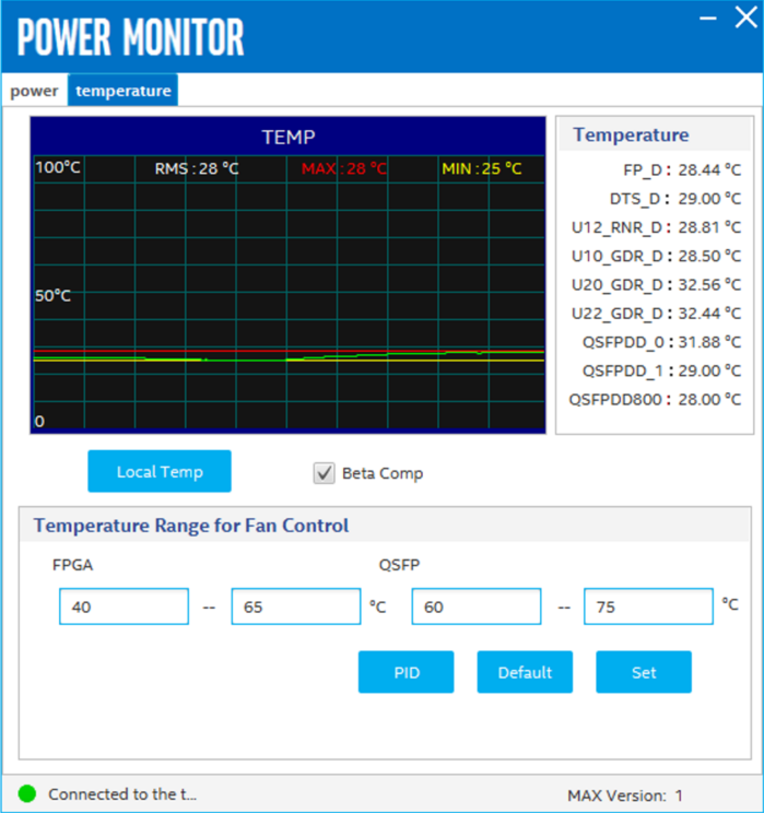
Temperature
Reads the temperature data from the FPGA die, diodes assembled on the PCB, and the QSFPDD modules.
Local Temp
Shows the temperature comparison of the local and remote temperature sensors.
Beta Comp
Enables Beta Compensation for the temperature sensing chips.
Temperature Range for Fan Control
Sets and displays the temperature range for the fan control.
Related Information