Visible to Intel only — GUID: mex1686141139191
Ixiasoft
1. About the Drive-on-Chip Design Example for Intel Agilex® 7 Devices
2. Features of the Drive-on-Chip Design Example for Intel Agilex 7 Devices
3. Getting Started with the Drive-on-Chip Design Example for Intel Agilex 7 Devices
4. Rebuilding the Drive-on-Chip Design Example for Intel Agilex 7 Devices
5. About the Scaling of Feedback Signals
6. Motor Control Software
7. Functional Description of the Drive-on-Chip Design Example for Intel Agilex 7 Devices
8. Signals
9. Registers
10. Design Security Recommendations
11. Document Revision History for AN 994: Drive-on-Chip Design Example for Intel Agilex 7 Devices
3.1. Software Requirements for the Drive-on-Chip Design Example for Intel Agilex 7 Devices
3.2. Hardware Requirements for the Drive-on-Chip Design Example for Intel Agilex 7 Devices
3.3. Downloading and Installing the Design
3.4. Setting Up your Development Board for the Drive-on-Chip Design Example for Intel Agilex 7 Devices
3.5. Configuring the FPGA Hardware for the Drive-on-Chip Design Example for Intel Agilex 7 Devices
3.6. Programming the Nios V/g Software to the Device for the Drive-on-Chip Design Example for Intel Agilex 7 Devices
3.7. Debugging and Monitoring the Drive-on-Chip Design Example for Intel Agilex 7 Devices with Python GUI
3.7.1. GUI Control Parameters Pane for the Drive-on-Chip Design Example for Intel Agilex 7 Devices
Trace
Current Control Parameters
Speed Control Parameters
Position Control Parameters
3.7.2. GUI Main Panes for the Drive-on-Chip Design Example for Intel Agilex 7 Devices
3.7.3. Tuning the PI Controller Gains
3.7.4. Controlling the Speed and Position Demonstrations
3.7.5. Monitoring Performance
7.3.6.1. DSP Builder for Intel FPGAs Model for the Drive-on-Chip Designs
7.3.6.2. Avalon Memory-Mapped Interface
7.3.6.3. About DSP Builder for Intel FPGAs
7.3.6.4. DSP Builder for Intel FPGAs Folding
7.3.6.5. DSP Builder for Intel FPGAs Design Guidelines
7.3.6.6. Generating VHDL for the DSP Builder Models for the Drive-on-Chip Designs
Visible to Intel only — GUID: mex1686141139191
Ixiasoft
3.7.1. GUI Control Parameters Pane for the Drive-on-Chip Design Example for Intel Agilex 7 Devices
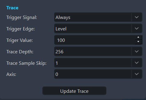
Trace
On the Trace section select:
- The waveform tracing by specifying a trigger.
- Axis to trace.
- Trace depth.
- A filename to store the trace data.
Click Update Trigger after making any changes. Click Start Trace to start tracing. Click the Waveform tab for trace display. When saving trace data to a file, the design overwrites the file with each trace. It does not append new traces to an existing file.
Figure 6. Trace
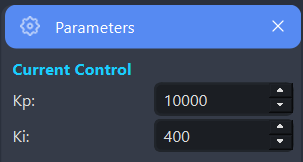
Current Control Parameters
Expand the Parameter tap in the bottom-left. On the Current Control, enter the proportional gain (Kp) and integral gain (Ki) coefficients for the current control loop. These quantities are preset to the correct values for the motor type configured in the application software. Click Update Parameters after making a change.
Figure 7. Current Control Parameters
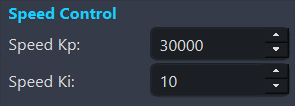
Speed Control Parameters
Expand the Parameter tap in the bottom-left. On the Speed Control area, enter the Speed Kp and Speed Ki coefficients for the speed control loop. These quantities are preset to the correct values for the motor type configured in the application software. Click Update Parameters after making a change.
Figure 8. Speed Control Parameters
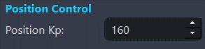
Position Control Parameters
Expand the Parameter tap in the bottom-left. On the Position Control area, enter the Position Kp coefficient for the position control loop. This quantity is preset to the correct values for the motor type configured in the application software. Click Update Parameters after making a change.
Figure 9. Position Control Parameters