Visible to Intel only — GUID: xkz1686147468947
Ixiasoft
1. About the Drive-on-Chip Design Example for Intel Agilex® 7 Devices
2. Features of the Drive-on-Chip Design Example for Intel Agilex 7 Devices
3. Getting Started with the Drive-on-Chip Design Example for Intel Agilex 7 Devices
4. Rebuilding the Drive-on-Chip Design Example for Intel Agilex 7 Devices
5. About the Scaling of Feedback Signals
6. Motor Control Software
7. Functional Description of the Drive-on-Chip Design Example for Intel Agilex 7 Devices
8. Signals
9. Registers
10. Design Security Recommendations
11. Document Revision History for AN 994: Drive-on-Chip Design Example for Intel Agilex 7 Devices
3.1. Software Requirements for the Drive-on-Chip Design Example for Intel Agilex 7 Devices
3.2. Hardware Requirements for the Drive-on-Chip Design Example for Intel Agilex 7 Devices
3.3. Downloading and Installing the Design
3.4. Setting Up your Development Board for the Drive-on-Chip Design Example for Intel Agilex 7 Devices
3.5. Configuring the FPGA Hardware for the Drive-on-Chip Design Example for Intel Agilex 7 Devices
3.6. Programming the Nios V/g Software to the Device for the Drive-on-Chip Design Example for Intel Agilex 7 Devices
3.7. Debugging and Monitoring the Drive-on-Chip Design Example for Intel Agilex 7 Devices with Python GUI
3.7.1. GUI Control Parameters Pane for the Drive-on-Chip Design Example for Intel Agilex 7 Devices
3.7.2. GUI Main Panes for the Drive-on-Chip Design Example for Intel Agilex 7 Devices
3.7.3. Tuning the PI Controller Gains
3.7.4. Controlling the Speed and Position Demonstrations
3.7.5. Monitoring Performance
7.3.6.1. DSP Builder for Intel FPGAs Model for the Drive-on-Chip Designs
7.3.6.2. Avalon Memory-Mapped Interface
7.3.6.3. About DSP Builder for Intel FPGAs
7.3.6.4. DSP Builder for Intel FPGAs Folding
7.3.6.5. DSP Builder for Intel FPGAs Design Guidelines
7.3.6.6. Generating VHDL for the DSP Builder Models for the Drive-on-Chip Designs
Visible to Intel only — GUID: xkz1686147468947
Ixiasoft
4.3. Generating and Building the Nios V/g BSP for the Drive-on-Chip Design Example
Before rebuilding the BSP, ensure that the settings.bsp file correctly generates. To generate BSP, use command line and niosv-bsp command.
The Drive-on-Chip Design Example includes an initial version of settings.bsp that contains parameters necessary to run the design. If you modify the Platform Designer's hardware, ensure you keep the integrity of the BSP settings file.
- After changing the BSP settings files, generate the BSP with the commands:
>> cd <project>/software/dniosv_subsystem>> niosv-bsp -q -E=./build/bsp/bsp_settings_export.tcl settings.bsp>> niosv-bsp -c --quartus-project=./../../quartus/top.qpf --qsys=./../../rtl/top_qsys.qsys --type=ucosii --bsp-dir=./build/bsp -x=./build/bsp/bsp_settings_export.tcl ./build/bsp/settings.bspThe code takes an existing template settings.bsp file and creates a new one based on it for the current project (updating locations of project) then builds the BSP.
- Run the following code to build the software:
>> cmake ./app -S ./app -G "Unix Makefiles" -B ./build/bin -DCMAKE_C_FLAGS=-O3 -DCMAKE_BUILD_TYPE=Release>> make -C ./build/bin>> elf2hex ./build/bin/app.elf -o ./build/bin/mem_init/dniosv_subsystem_cpu_ram_cpu_ram.hex -r 4 -b 0x20000000 -w 32 -e 0x203FFFFFThe app.elf file is in <project>/software/dniosv_subsystem/build/bin
- Compile the software to update the .sof file, so it contains the new binaries (hex) for memory initialization (refer to Compiling the Hardware in the Intel Quartus Prime Software)
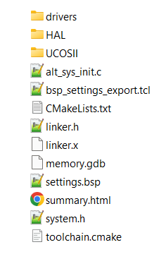
Figure 13. Directory StructureThe figure shows the BSP directory structure with µC/OS-II operating system.

- Program or configure the software application refer to Configuring the FPGA Hardware for the Drive-on-Chip Design Example for Intel Agilex 7 Devices or Programming the NiosV/g Software to the Device for the Drive- on-Chip Design Example for Intel® Agilex™ 7 Devices