Visible to Intel only — GUID: hmx1524129425035
Ixiasoft
1. Quick Start Guide
2. 10M/100M/1G Ethernet Design Example
3. 1G Ethernet Design Example with IEEE 1588v2 Feature
4. 2.5G Ethernet Design Example
5. 2.5G Ethernet Design Example with IEEE 1588v2 Feature
6. 10G Ethernet Design Example
7. 10M/100M/1G/2.5G/5G/10G (USXGMII) Ethernet Design Example
8. 10M/100M/1G/2.5G/5G/10G (USXGMII) Ethernet Design Example with IEEE 1588 Design Example
9. Interface Signals Description
10. Configuration Registers Description
11. Low Latency Ethernet 10G MAC Intel® FPGA IP Design Example User Guide: Agilex™ 5 FPGAs and SoCs Archives
12. Document Revision History for the Low Latency Ethernet 10G MAC Intel® FPGA IP Design Example User Guide: Agilex™ 5 FPGAs and SoCs
Visible to Intel only — GUID: hmx1524129425035
Ixiasoft
8.4.1. Test Case—Design Example with the IEEE 1588v2 Feature
The simulation test case performs the following steps:
- Starts up the design example with an operating speed of 10G.
- Configures the MAC, PHY, and FIFO buffer for both channels.
- Asserts global reset (i_rst_n) to reset the Multirate PHY IP.
- Waits until resets acknowledgement. The o_rst_ack_n signals goes low.
- Deasserts the global reset.
- Waits until the design example asserts the channel_tx_ready and channel_rx_ready signals for each channel.
- Waits until the deterministic latency measurement (indicated by tx_measure_valid and rx_measure_valid bit of register 0x420) of PHY IP is completed.
- Calculates the datapath deterministic latency and configures PTP registers
- Sends the following packets:
- Non-PTP
- No VLAN, PTP over Ethernet, PTP Sync Message, 1-step PTP
- VLAN, PTP over UDP/IPv4, PTP Sync Message, 1-step PTP
- Stacked VLAN, PTP over UDP/IPv6, PTP Sync Message, 2-step PTP
- No VLAN, PTP over Ethernet, PTP Delay Request Message, 1-step PTP
- VLAN, PTP over UDP/IPv4, PTP Delay Request Message, 2-step PTP
- Stacked VLAN, PTP over UDP/IPv6, PTP Delay Request Message, 1-step PTP
- Repeats steps 5 to 8 for 100M, 1G, 2.5G, and 5G.
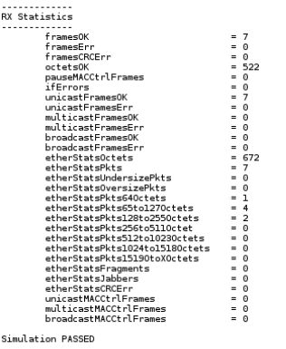
When simulation ends, the values of the MAC statistics counters are displayed in the transcript window. The transcript window also displays PASSED if the RX Avalon® streaming interface of channel 0 received all packets successfully, all statistics error counters are zero, and the RX MAC statistics counters are equal to the TX MAC statistics counters.
Figure 42. Sample Simulation Output

