AN 995: Three-phase Boost Bidirectional AC-DC and LLC DC-DC Converter for EV Charging Design Example
Visible to Intel only — GUID: hce1691145478823
Ixiasoft
Visible to Intel only — GUID: hce1691145478823
Ixiasoft
3.2. Simulink* Model
You simulate the load current as a square waveform with positive and negative values, generating current and voltage waveforms in the design. When the load current switches, you can examine the transient current and voltage signals using the rectifier.stp file in Signal Tap logic analyzer within the Intel® Quartus® Prime software.
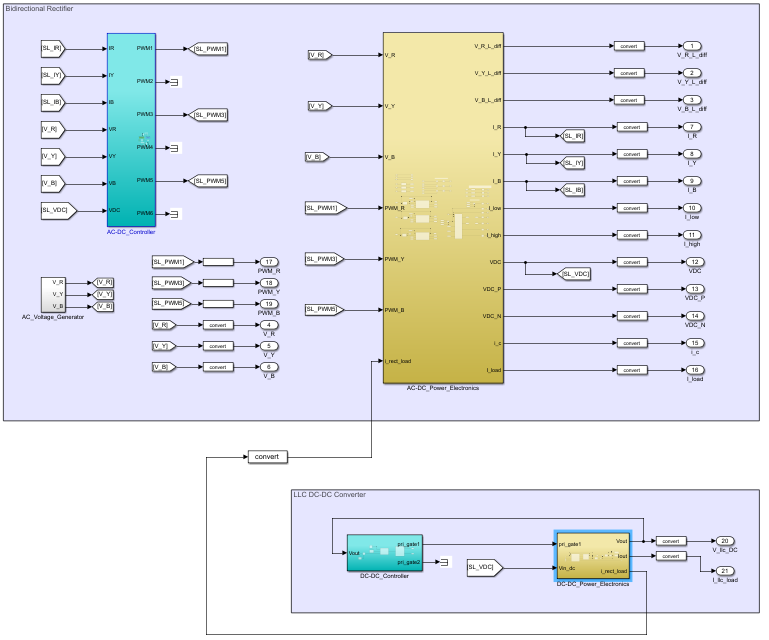
The bidirectionalAC-DC and LLC DC-DC converter has the portion of the simulation for which the design generates VHDL code. The design defines the outputs in the top-level model file using the blocks' in-port or out-port interfaces for the VHDL code. The MATLAB Simulink in-port and out-port signals define the VHDL signal names, and the VHDL data formats are the signal formats you typically set with the convert block.