Visible to Intel only — GUID: pev1691146648228
Ixiasoft
1. About the Three-phase Boost Bidirectional AC-DC and LLC DC-DC Converter for Electric Vehicle (EV) Charging Design Example
2. Getting started with the Design Example
3. Functional Description
4. Top-level VHDL Wrapper
5. Simulink Simulation Results
6. Document Revision History for AN 995: Three-phase Boost Bidirectional AC-DC and LLC DC-DC Converter for EV Charging Design Example
Visible to Intel only — GUID: pev1691146648228
Ixiasoft
3.2.1.1. PWM Controller
The The Three-phase Boost Bidirectional AC-DC and LLC DC-DC Converter for EV Charging design example PWM controller for the power switches that generate the PWM (power transistor switching controller) outputs comprises an outer proportional integral (PI) voltage control loop surrounding two internal current PI controllers.
Figure 16. PWM Controller Implemented in Simulink with HDL Coder Blocks

An external reference voltage (VDC), the capacitor voltage, or an output voltage (up to 800 V) provides the output reference voltage. The output voltages are initially subtracted from the reference voltage, and the current reference controls it. Direct quadrature (DQ) synchronous reference frame voltages are achieved at the control output. Normalize these two voltage values by a factor of 1 (shift-left logical) and 1/800 to get a waveform that you can use in the space vector PWM (SVPWM) block. After normalization, the design converts the values from the DQ frame to the alpha-beta frame (orthogonal stationary). It uses thems in the SVPWM block to control the switching of the power transistors in the six-switch converter module.
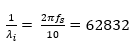
To find the values of the PI constants, refer to the Analysis and Control of Three-Phase PWM Rectifier for Power Factor Improvement of IM Drive 1 paper for the following formulas:
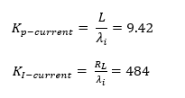
where:
-
- L is the input inductance.
- RL is the associated resistance.
Similarly, you can calculate voltage loop constants as follows:
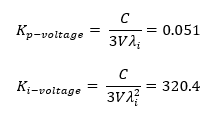
where:
- C is the DC link capacitance.
- V is the input RMS voltage.
Even though the values calculated using the equations provide a good control response, manual tuning is necessary to achieve the desired overshoot and settling time. After manual tuning, you can find the following values for the constants in the Simulink model blocks:
- Kp-voltage = 0.15
- Ki-voltage = 22 Ts
- Kp-current1 = 25
- Ki-current1 = 500 Ts
- Kp-current2 = 25
- Ki-current2 = 500 Ts
Note: Consider Ts = 50 ns and the circuit is running at 20 MHz in the discrete domain.
1 P. Scholar, ‘Analysis and Control of Three Phase PWM Rectifier for Power Factor Improvement of IM Drive’, International Journal of Innovations in Engineering and Technology, vol. 10, no. 2, p. 7, 2018