AN 995: Three-phase Boost Bidirectional AC-DC and LLC DC-DC Converter for EV Charging Design Example
ID
784593
Date
9/15/2023
Public
Visible to Intel only — GUID: fdi1690297021576
Ixiasoft
1. About the Three-phase Boost Bidirectional AC-DC and LLC DC-DC Converter for Electric Vehicle (EV) Charging Design Example
2. Getting started with the Design Example
3. Functional Description
4. Top-level VHDL Wrapper
5. Simulink Simulation Results
6. Document Revision History for AN 995: Three-phase Boost Bidirectional AC-DC and LLC DC-DC Converter for EV Charging Design Example
Visible to Intel only — GUID: fdi1690297021576
Ixiasoft
2.5. Programming the Board with the Design
Before programming the board with theThree-phase Boost Bidirectional AC-DC and LLC DC-DC Converter for EV Charging design example, install the design.
- Click Processing > Start Compilation.
- Connect the relevant USB cable from the USB connector on the development board to your computer.
- J12 for Intel® MAX® 10 FPGA Development Kit
- J37 for Cyclone® V SoC Development Kit
- Apply power to the development board.
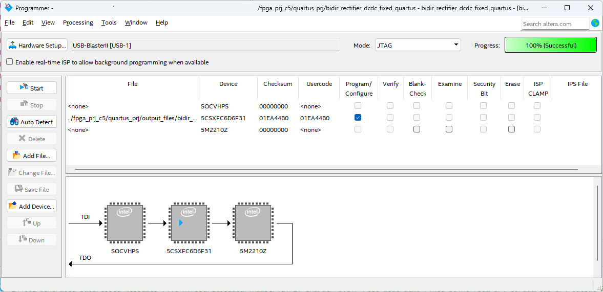
- After compilation ends, click Tools > Programmer to program your Intel® MAX® 10 Development Kit or Cyclone® V SoC Development Kit. Use the Auto Detect feature if necessary.
- Select the master_image/bidir_rectifier_dcdc_fixed_quartus.sof file or your newly generated output_files/bidir_rectifier_dcdc_fixed_quartus.sof file.
Figure 3. Programming the BoardThe figure shows the programmer for Cyclone® V SoC Development Kit FPGA (5CSXFC6D6F31).

- Turn on Program/Configure in the table.
- Click Start. The Progress bar shows in green 100% (Successful).