AN 995: Three-phase Boost Bidirectional AC-DC and LLC DC-DC Converter for EV Charging Design Example
Visible to Intel only — GUID: ucw1690297158374
Ixiasoft
Visible to Intel only — GUID: ucw1690297158374
Ixiasoft
2.5.1. Running the Design
- In the Intel® Quartus® Prime software click Tools > Signal Tap Logic Analyzer.
- In the Signal Tap Logic Analyzer window, in the top right corner, click Setup to select USB-BlasterII.
Figure 4. Hardware Setup

- Select the appropriate FPGA device.
- For the Intel® MAX® 10 Development Kit select @1: 10M50DA(.ES)/10M50DC (0x031050DD)
- For the Cyclone® V SoC Development Kit, select @2: 5CSEBA6(.ES)/5CSEMA6/..(0x02D020DD).
- In the Signal Tap Logic Analyzer window, select the Data tab and click
 .
Figure 5. Signal Tap Logic Analyzer Waveform
.
Figure 5. Signal Tap Logic Analyzer Waveform
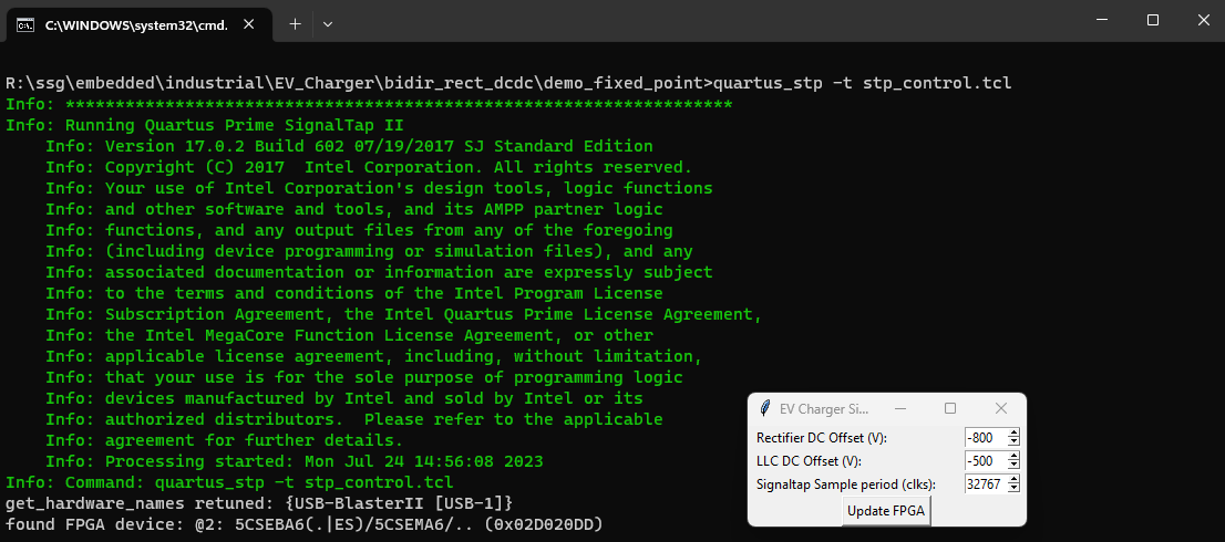
- Navigate to the matlab/Simulink directory and double-click the run_stp_control.bat file to adjust the sampling resolution.
- In the EV Charger dialog box, set VDC Offset (V) to -800, LLC DC Offset to -500 and Signaltap Sample period (clks) to 32767.
Figure 6. Changing VDC Offset and Signaltap Sample Period
- Return to the Signal Tap logic analyzer window and click .
Figure 7. Scaled Output Waveform in the Signal Tap Logic Analyzer

In the model, the AC-DC converter output DC Voltage (VDC) is regulated to 800V. Setting the VDC Offset to -800 V allows you to see the maximum range in the Signal Tap logic analyzer.
In the model, the DC-DC converter output DC Voltage (VDC), is regulated to 500V. Setting the VDC Offset in this GUI to -500 V allows you to see the maximum range in the Signal Tap logic analyzer.
The SignalTap Sample Period sets the period of a counter, which enables waveforms sampling. A value of n results in samples every n-1 clock cycles. So, a value of 0 samples every clock cycle results in no aliasing with a very short visible period. The analyzer shows the value of 32767 in step 28 samples every 32768 cycles. The PWM signals are highly aliased, but you can see a long time frame.
You can run the GUI script from the Intel® Quartus® Prime software Tcl console with the following command:exec quartus_stp -t ../../stp_control.tcl &
Note: The ../../ path depends on the current directory of the Intel® Quartus® Prime software.