AN 995: Three-phase Boost Bidirectional AC-DC and LLC DC-DC Converter for EV Charging Design Example
ID
784593
Date
9/15/2023
Public
Visible to Intel only — GUID: kuf1691066932935
Ixiasoft
1. About the Three-phase Boost Bidirectional AC-DC and LLC DC-DC Converter for Electric Vehicle (EV) Charging Design Example
2. Getting started with the Design Example
3. Functional Description
4. Top-level VHDL Wrapper
5. Simulink Simulation Results
6. Document Revision History for AN 995: Three-phase Boost Bidirectional AC-DC and LLC DC-DC Converter for EV Charging Design Example
Visible to Intel only — GUID: kuf1691066932935
Ixiasoft
2.6.2. Generating HDL and QPF Using MATLAB GUI Tools
You generate an Intel® Quartus® Prime software project and VHDL code for the fixed-point model in the bidir_rectifier_dcdc.slx file for the Three-phase Boost Bidirectional AC-DC and LLC DC-DC Converter for EV Charging design.
- Open the MATLAB model in the matlab/Simulink/bidir_rectifier.slx directory. The MATLAB and Simulink window opens.
- In the MATLAB interface, select the parameters.m file and click Run. This sets some necessary variables to synthesize the model.
- Launch the Simulink window where you can see the synthesized model that generates an Intel® Quartus® Prime software project and VHDL code (bidir_rectifier_dcdc_fixed).
- In the Simulink window, navigate to the HDL CODE tab and click Workflow Advisor. Ignore the warning of a missing ./top.vhd.
Figure 9. Workflow Advisor and Simulink GUI
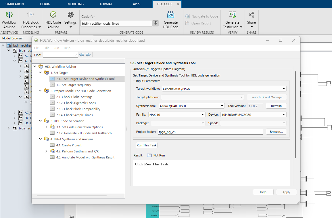
- Expand the HDL Workflow Advisor tasks menu in the left-hand pane.
- Select 1.1 Set Target Device and Synthesis Tool to configure the target FPGA device and either:
- For Intel® MAX® 10 FPGA Development Kit: select the value for Family as MAX 10 and Device as 10M50DAF484C6GES.
- For Cyclone® V SoC Development Kit: select the value for Family as Cyclone V and Device as 5CSXFC6D6F31C6.
- Change the Project folder to a desired project location and name.
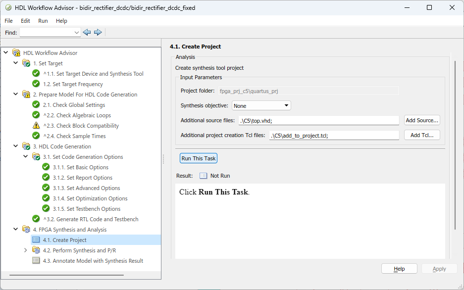
- In the left-hand pane, select 4.1 Create Project.
- For Additional source files, select either:
- For Intel® MAX® 10 FPGA Development Kit: <local_path>/M10/top.vhd
- For Cyclone® V SoC Development Kit: <local_path>/C5/top.vhd
- For Additional project creation Tcl files, select either:
- For Intel® MAX® 10 FPGA Development Kit: <local>/matlab/Simulink/m10/add_to_project.tcl
- For Cyclone® V SoC Development Kit: <local>/matlab/Simulink/c5/add_to_project.tcl
- Run the tasks by clicking Run This Task.
Figure 10. Running tasks in HDL Workflow Advisor
- Navigate to the project directory that you selected in step 4. The newly created Intel® Quartus® Prime software project is in the quartus_prj directory and the generated VHDL code for the Simulink model is located in the hdlsrc directory.
- Navigate to the quartus_prj directory and open the bidir_rectifier_dcdc_fixed_quartus.qpf file with the Intel® Quartus® Prime software.
- Compile the design, generate a .sof file, and program your board as described in Programming the Board with the Design .
- Use Signal Tap logic analyzer to view the waveforms created by the generated VHDL code programmed in your board.
Related Information