Instantiate a Memory Tester Subsystem as a Generic Component
You can instantiate the memory tester subsystem as a generic component (an empty entity with only interfaces defined). When integrating a memory tester subsystem with a processor subsystem and an EMIF controller only the interfaces of the memory tester subsystem are significant.
Instantiation of a generic component does not prevent the completion of other parts of the design. This feature provides a lot of flexibility in the design, and is especially beneficial for large and team-based designs. You need only verify that, when adding the entity implementation, the entity interfaces match the interfaces defined for the generic component.
To instantiate a generic component:
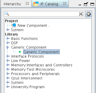
- In the IP Catalog, double-click Generic Component.
Figure 21. IP Catalog Generic Component

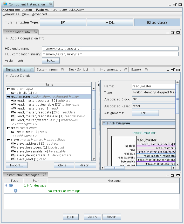
The Component Instantiation tab contains three implementation types: IP, HDL, and Blackbox. When you add a generic component, Blackbox is the default.
- Change the HDL entity name and HDL compilation library to memory_tester_subsystem.
Figure 22. Component Instantiation Tab for memory_tester_subsystem Generic Component
- To add the component, click Finish.
- Right-click the name of the top_system_generic_component_0 component and click Rename. Type memory_tester_subsystem.
Platform Designer provides many features to help you add interfaces and signals for a generic component. The following steps, 1-11, showcase how to add signals manually, by using Mirror or Clone, and how to change parameters. In the final steps, you are going to import a complete interface definition from an .ipxact file.
Platform Designer provides many ways to help you add interfaces easily and efficiently.
- Click .
- Select the memory_tester_subsystem component. The instantiation information appears in the Component Instantiation tab.
- Click the Signals & Interfaces tab. You can add interfaces manually, Import from an IP-XACT file, Mirror, or Clone from existing interfaces in the system.
- Click << add interface>> and select Clock Input from the drop down list.
- To change the name of the interface, in the Name field, type clk.
- Click <<add signal>> and choose clk.
- Repeat steps 4-6 to add a Reset Input interface and signal, and rename it reset.
- Click Apply.
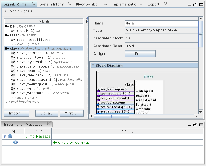
Figure 23. Signal and Interface Options for memory_tester_subsystem
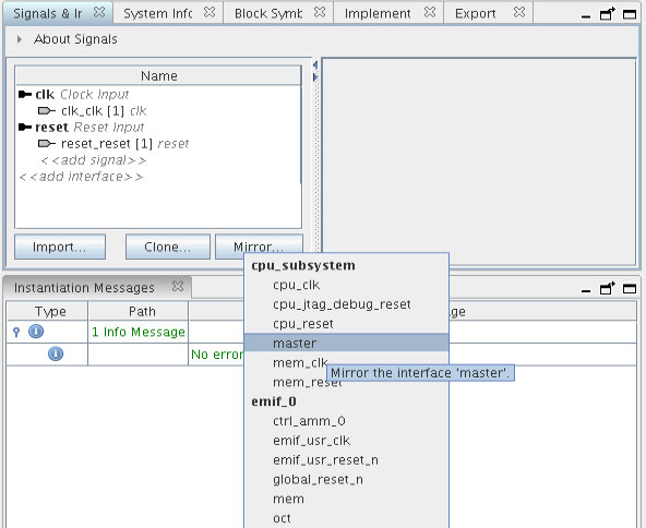
Apart from clock and reset, the design also requires an Avalon-MM slave interface to communicate with the processor subsystem. It could be tedious to add Avalon-MM slave interface manually since there are address bus, data bus, and many other parameter settings to configure. An easier way is to use the Mirror feature.
- Click Mirror and choose the master interface of cpu_subsystem to add a slave interface.
Figure 24. Create Mirror of Interface 'master'

- You can resolve the errors that appear in the Instantiation Messages box by assigning Associated Clock and Associated Reset to the clk and reset interfaces in the parameter editor.

- Locate the Maximum pending read transactions box under Pipelined Transfers and change that value to 4.
- Click Import and choose memory_tester_subsystem_bb.ipxact to add the interfaces.
- To complete the import step, click Apply.
Figure 25. Results of Importing memory_tester_subsystem_ bb.ipxact

Click the Implementation tab to create a Platform Designer template with interface requirements setup to implement the memory tester subsystem. You can also create an HDL template with ports defined.
- Click to create the memory_tester_ subsystem.qsys file in the <project folder>.
- Click to create the memory_tester_ subsystem.v file in the <project folder>.
The Export tab allows you to export the interfaces and requirements to an .ipxact or a _hw.tcl file, however, this feature is not used in this project.
