Visible to Intel only — GUID: qfh1476250931974
Ixiasoft
2.1.1. Constructing Communication Links in the Link Designer Module
2.1.2. Link and Simulation Setting
2.1.3. Transmitter Setting
2.1.4. Receiver Setting
2.1.5. IBIS-AMI Wrapper
2.1.6. Channel Setting
2.1.7. Batch Channel Simulation Configuration
2.1.8. Crosstalk Aggressor Transmitter Setting
2.1.9. Repeater and Retimer Configurations
2.1.10. Noise Source Link Component
2.1.11. System Options
2.1.12. Project Management Functions
2.1.13. Archiving and Unarchiving Projects
2.1.14. Device Model Importer
2.1.15. Analysis Functions and Pre-Simulation and Pre-Analysis Checklists
2.1.16. COM Analysis
Visible to Intel only — GUID: qfh1476250931974
Ixiasoft
2.1.9.1. Repeater/Retimer RX Configuration
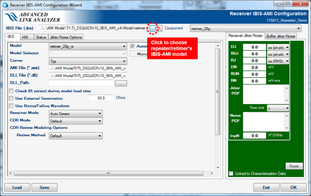
- IBIS Files: Click the file open button next to the IBIS File text box to select an IBIS model file. Intel® Advanced Link Analyzer scans through the IBIS file and allocates all available receiver components and models. If Intel® Advanced Link Analyzer encounters any of the following issues in opening or interpreting the IBIS-AMI model, a warning message is shown.
- No receiver component or model can be located.
- The DLL for the computer platform cannot be located. Note that the IBIS-AMI model is platform dependent. For example, a 32-bit DLL is required to simulate in a 32-bit link simulator. A 64-bit DLL is required to simulate in a 64-bit simulator. A 32-bit DLL cannot simulate with a 64-bit DLL in the same simulation.
- The DLL occupies so much memory that Intel® Advanced Link Analyzer was not able to load it. However, Intel® Advanced Link Analyzer might be able to run the simulation with such a DLL because of memory allocation differences in the Intel® Advanced Link Analyzer GUI and the simulation engine.
- Component: Select an IBIS component from the IBIS model.
- IBIS tab
- Model: Select a device model within a component of an IBIS model.
- Model Selector: Select a model from the model selector list.
- Corner: Select the corner type of a device model. The choices are Typ, Min, and Max.
- AMI File: Shows the AMI file specified in the IBIS model.
Note: Intel® Advanced Link Analyzer currently only supports device models with AMI modeling components.
- DLL File: Shows the DLL file specified in the IBIS model.
- Use External Termination: Indicates that an external termination is used in the simulation. The external termination (single-ended) is specified in the text box on the right. The default setting is not using external termination and the default external termination (if applicable) is 50 ohms (single-ended).
Note: Intel® Advanced Link Analyzer automatically enables the external termination option when it detects that the IBIS-AMI model is using [series pin mapping] with [R series] configuration.
- Automatic Jitter/Noise Update : Allows automatic jitter/noise updates from the IBIS-AMI model (available for models which are compliant with IBIS-AMI 6.0 and later).
Note: If you noticed very slow GUI response with certain IBIS-AMI models, turn off Automatic Jitter/Noise Update to see if the condition improves. You can import jitter/noise number using Manual Jitter/Noise Update.
- Manual Jitter/Noise Update: When the Automatic Jitter/Noise Update option is disabled, turning on this option allows you to manually update the jitter/noise figures from the IBIS-AMI model (available for models which are compliant with IBIS-AMI 6.0 and later).
- DLL Path: Specify a folder or path name where the supporting files of an IBIS-AMI model are stored. Refer to the IBIS standards for details.
- User Rising/Falling Waveform: Internal testing feature. Do not use and left as is.
- Receiver Mode: Used to select the function or behavior of the receiver model. Select Auto Detect to let Intel® Advanced Link Analyzer determine the operating mode based on the model’s capabilities. Select Repeater to force Intel® Advanced Link Analyzer to use this model as a repeater’s equalization stage. Select Retimer to ask Intel® Advanced Link Analyzer to treat, if possible, this model as the equalizer/CDR stage of a retimer. The default setting is Auto Detect.
- CDR Retime Modeling Options / Retime Method: Select Precision to tell Intel® Advanced Link Analyzer to assume the return clock ticks are precise sufficiently that accumulated clock time equal the simulation time line. Select Speed to ask the simulation engine to process the returned clock times with a limited window of time frame. Select Default is the same as the Speed option.
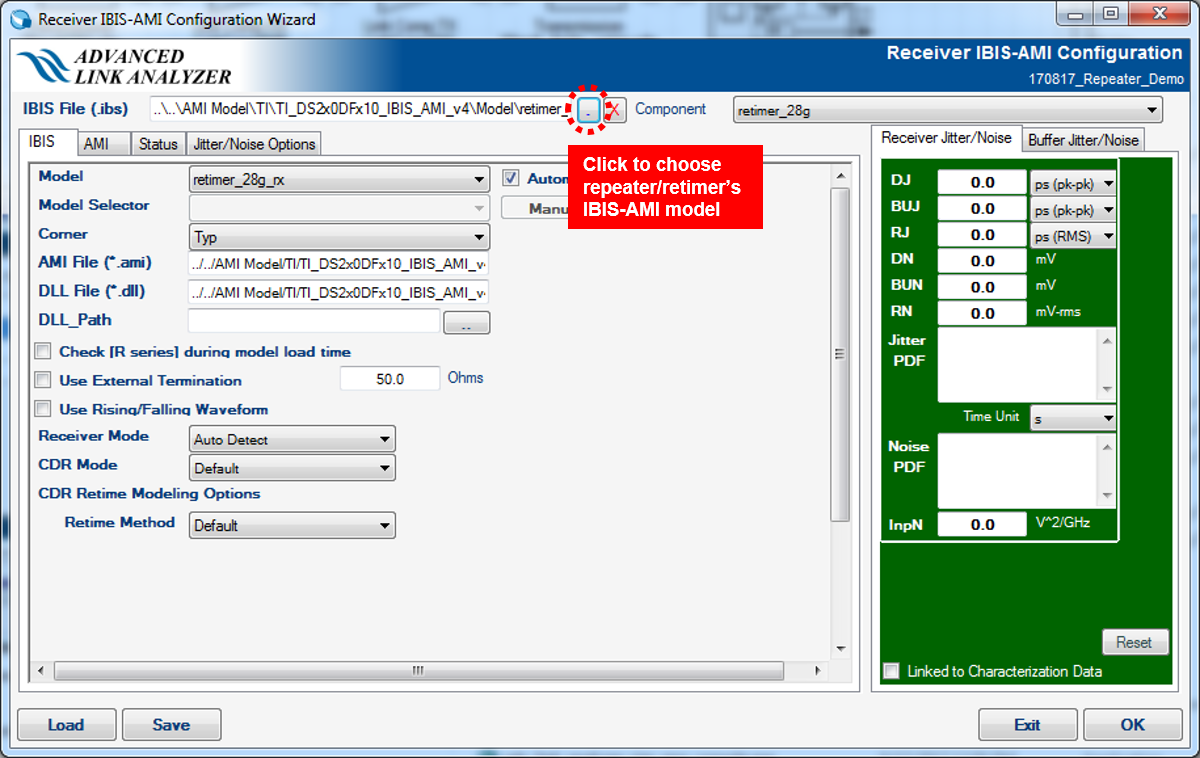
- AMI tab: Refer to IBIS-AMI Receiver in the Receiver Options section for details.
- Jitter/Noise: Refer to IBIS-AMI Receiver in the Receiver Options section for details.
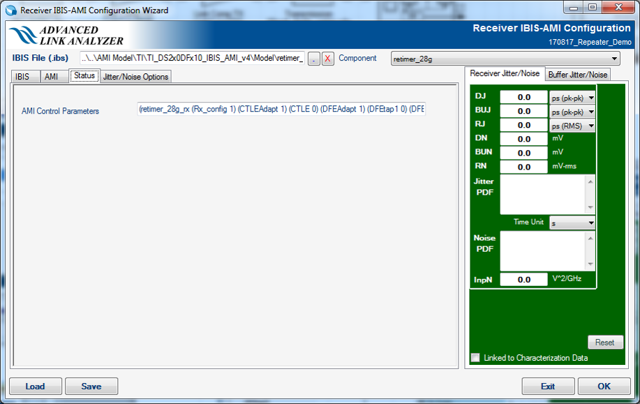
- Status tab: Refer to IBIS-AMI Receiver in the Receiver Options section for details.
- Jitter/Noise Options: Internal use only. Do not use and let it remain in its default state.
Figure 84. Repeater/Retimer RX IBIS-AMI model configuration


Figure 85. Repeater/Retimer RX model’s AMI


Figure 86. Repeater/Retimer RX model’s Status Tab


Related Information