Visible to Intel only — GUID: uvc1587070837805
Ixiasoft
2.1.1. Constructing Communication Links in the Link Designer Module
2.1.2. Link and Simulation Setting
2.1.3. Transmitter Setting
2.1.4. Receiver Setting
2.1.5. IBIS-AMI Wrapper
2.1.6. Channel Setting
2.1.7. Batch Channel Simulation Configuration
2.1.8. Crosstalk Aggressor Transmitter Setting
2.1.9. Repeater and Retimer Configurations
2.1.10. Noise Source Link Component
2.1.11. System Options
2.1.12. Project Management Functions
2.1.13. Archiving and Unarchiving Projects
2.1.14. Device Model Importer
2.1.15. Analysis Functions and Pre-Simulation and Pre-Analysis Checklists
2.1.16. COM Analysis
Visible to Intel only — GUID: uvc1587070837805
Ixiasoft
2.1.3.7. Jnu/Jrms/EOJ Analysis
Click Jnu/Jrms Calc or select Jnu/Jrms Analysis from the Analysis pull-down menu to perform PAM4 Jnu/Jrms/EOJ analysis. A Jnu/Jrms/EOJ pre-analysis GUI guides the analysis. There are two jitter analysis methods:
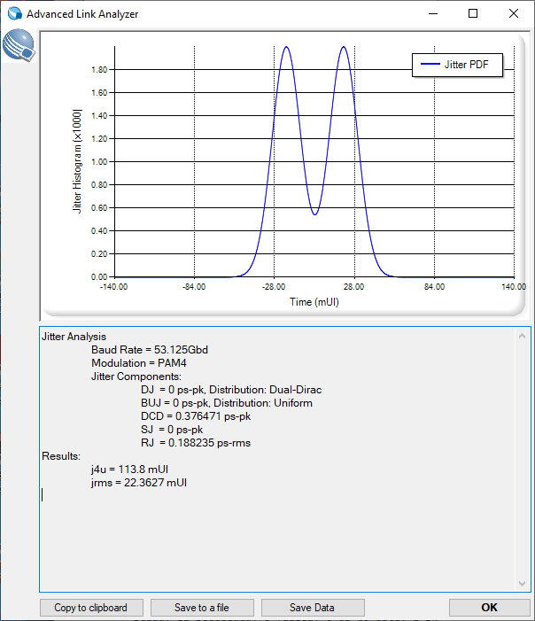
Jitter PDF: Jitter PDF method gets jitter information from users or the TX model. It calculates the Jnu/Jrms at target BER using jitter component convolutions. The Option selection is ignored for Jitter PDF method.
Note: PDF method does not support EOJ analysis.
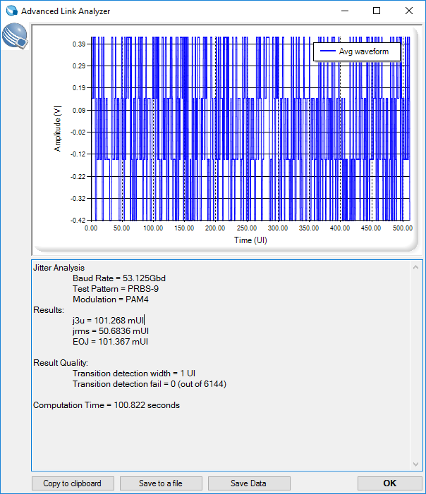
Waveform: The calculation and analysis are implemented according to IEEE 802.3 (50 Gbps 802.3cd and 100 Gbps 802.3ck) and OIF CEI (56G and 112G) standards. The result provides an indication of transmitter or channel output quality. The averaged waveform is displayed. The Jnu/Jrms/EOJ calculation is performed at the end of the channel. If you want to analyze the transmitter’s jitter performance, you can use an ideal channel, for example, Ideal.s4p in Intel® Advanced Link Analyzer’s Database folder, to perform the analysis. The PAM4 jitter analysis supports both PRBS13Q/QPRBS-13CEI and PRBS-9Q analysis flows where PRBS13Q/QPRBS-13CEI is used for Jnu/Jrms calculation and PRBS-9Q is used for EOJ extractions per the latest IEEE 802.3ck trending specifications.
Note: PAM4 jitter analysis engine calculates Jun/Jrms/EOJ values for the selected test pattern. You might need to run the jitter analysis twice to collect, for example, Jnu/Jrms with PRBS13Q and EOJ with PRBS9Q test pattern.
Figure 42. Jnu/Jrms/EOJ Analysis Example (Jitter PDF Method)


You can customize Jnu/Jrms analysis to suit specific transmitter configurations. See Analysis Functions and Pre-Simulation and Pre-Analysis Checklist for details.
Figure 43. Jnu/Jrms/EOJ Analysis Example (Waveform Method)


Related Information