Visible to Intel only — GUID: hco1423076597844
Ixiasoft
Visible to Intel only — GUID: hco1423076597844
Ixiasoft
7.6.1. Position, Speed, and Current Control for AC Motors
The model file is psc_ctrl.mdl. Also, an equivalent fixed-point design, psc_ctrl_fixed.mdl, exists. To change the precision this design uses, refer to the setup_position_speed_current_controller_fixed.m script.
Functional Description
An encoder measures the rotor position in the motor, which the FPGA then reads. An analog-to-digital converter (ADC) measures current feedback, which the FPGA then reads.
Each of the FOC, speed, and position feedback loops use a simple PI controller to reduce the steady state error to zero. In a real-world PI controller, you may also need to consider integrator windup and tune the PI gains appropriately. The feedback loops for the integral portion of the PI controllers are internal to the design.
The example assumes you sample the inputs at a rate of 100 kHz and the FPGA clock rate is 100 MHz (suitable for Cyclone IV devices). ALU folding reduces the resource usage by sharing operators such as adders, multipliers, cosine. The folding factor is set to 100 to allow each operator to be timeshared up 100 times, which gives an input sample rate of 1 Msps, but as the real input sample rate is 100 ksps, only one out of every ten input timeslots are used. DSP Builder identifies the used timeslots when valid_in is 1. Use valid_in to enable the latcher in the PI controller, which stores data for use in the next valid timeslot. The valid_out signal indicates when the ChannelOut block has valid output data. You can calculate nine additional channels on the samedesign without incurring extra latency (or extra FPGA resources).
You should adjust the folding factor to see the effect it has on hardware resources and latency. To adjust, change the Sample rate (MHz) parameter in the ChannelIn and ChannelOut blocks of the design either directly or change the FoldingFactor parameter in the setup script. For example, a clock frequency of 100 MHz and sample rate of 10 MHz gives a folding factor of 10. Disabling folding, or setting the factor to 1, results in no resource sharing and minimal latency. Generally, you should not set the folding factor greater than the number of shareable operators, that is, for 24 adders and 50 multipliers, use a maximum folding factor 50.
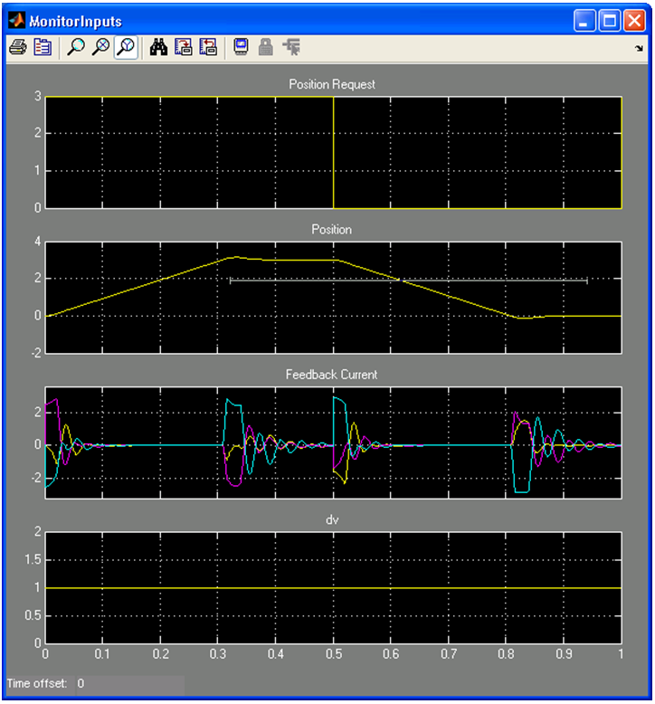
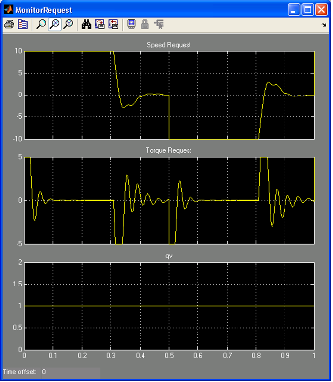
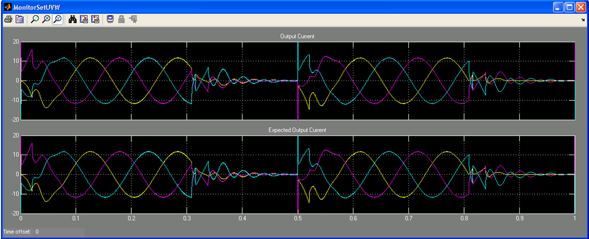
The control algorithm, with the FOC, position, speed, control loops, vary the desired position across time. The three control loops are parameterized with minimum and maximum limits, and Pl values. These values are not optimized and are for demonstrations only.
Resource Usage
| Folding Factor | Add and Sub Blocks | Mult Blocks | Cos Blocks | Latency |
|---|---|---|---|---|
| No folding | 22 | 22 | 4 | 170 |
| >22 | 1 | 1 | 1 | 279 |
The example uses floating-point arithmetic that automatically avoids arithmetic overflow, but you can implement it in a fixed-point design and tune individual accuracies while manually avoiding overflows.
Hardware Generation
When hardware generation is disabled, the Simulink system simulates the design at the external sample rate of 100 kHz, so that it outputs a new value once every 100 kHz. When hardware generation is enabled, the design simulates at the FPGA clock rate (100 MHz), which represents real-life latency clock delays, but it only outputs a new value every 100 kHz. This mode slows the system simulation speed greatly as the model is evaluated 1,000 times for every output. The setup script for the design example automatically detects whether hardware generation is enabled and sets the sample rates accordingly. The example is configured with hardware generation disabled, which allows fast simulations. When you enable hardware generation, set a very small simulation time (for example 0.0001 s) as simulation may be very slow.

