Visible to Intel only — GUID: ewo1418431676058
Ixiasoft
Visible to Intel only — GUID: ewo1418431676058
Ixiasoft
4.1.9.1. Implementing a 1588 System That Includes a 25G Ethernet Intel FPGA IP Core
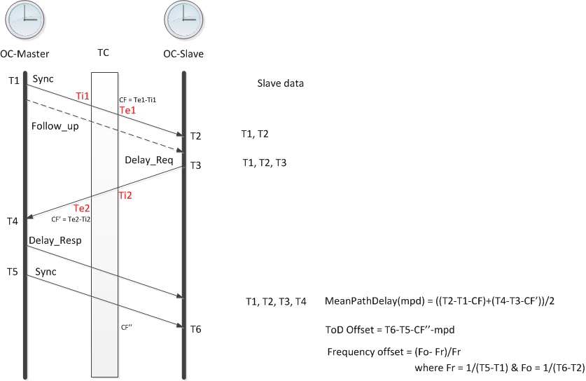
The 1588 specification in IEEE 1588-2008 Precision Clock Synchronization Protocol for Networked Measurement and Control Systems Standard describes various systems you can implement in hardware and software to synchronize clocks in a distributed system by communicating offset and frequency correction information between master and slave clocks in arbitrarily complex systems. A 1588 system that includes the 25G Ethernet Intel FPGA IP core with 1588 PTP functionality uses the incoming and outgoing timestamp information from the IP core and the other modules in the system to synchronize clocks across the system.
The 25G Ethernet Intel FPGA IP core with 1588 PTP functionality provides the timestamp manipulation and basic update capabilities required to integrate your IP core in a 1588 system. You can specify that packets are PTP packets, and how the IP core should update incoming timestamps from the client interface before transmitting them on the Ethernet link. The IP core does not implement the event messaging layers of the protocol, but rather provides the basic hardware capabilities that support a system in implementing the full 1588 protocol.
