Visible to Intel only — GUID: krv1668177594861
Ixiasoft
1. About the High Bandwidth Memory (HBM2E) Interface Agilex™ 7 FPGA IP User Guide
2. Introduction to High Bandwidth Memory
3. Agilex™ 7 M-Series HBM2E Architecture
4. Creating and Parameterizing the High Bandwidth Memory (HBM2E) Interface FPGA IP
5. High Bandwidth Memory (HBM2E) Interface FPGA IP Interface
6. High Bandwidth Memory (HBM2E) Interface FPGA IP Performance
7. Debugging the High Bandwidth Memory (HBM2E) Interface FPGA IP
8. Document Revision History for High Bandwidth Memory (HBM2E) Interface FPGA IP User Guide
A. High Bandwidth Memory (HBM2E) Interface FPGA IP Quartus® Prime Software Flow
Visible to Intel only — GUID: krv1668177594861
Ixiasoft
A.1. Initiators Placement Recommendations
Use the Interface Planner to modify the default physical placement of initiators. You can also use this tool to specify the placements of the UIB blocks, such as the HBM2E controller.
It is your responsibility to ensure that any placements that you specify are consistent with each other.
Follow these steps to change the locations of initiators:
- Launch the Quartus® Prime Pro Edition software.
- Click Tools > Interface Planner. The Interface Planner appears.
- On the Flow tab, click Initialize Interface Planner.
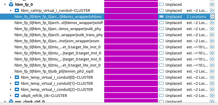
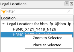
- On the Plan tab, you can see the different modules of HBM2E IP under the ed_synth hierarchy. To choose the correct location of the HBM2E instance, right-click the HBM controller instance and select Generate Legal Locations of Selected Element. The system reports the legal locations at which you can place your HBM controller.
For each instance, there are two legal locations at which you can place the controller: top or bottom. Right-click the location where you want to place the controller and click Place at Selected. The following figure shows the bottom controller selected:
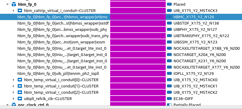
- Once the HBM2E controller is placed, click Autoplace Fixed three times to fix the locations of the UIB PHY, targets, and NoC clock control block based on the controller location. By this step, you see all the instances of your HBM2E IP and NoC clock control that have been placed.
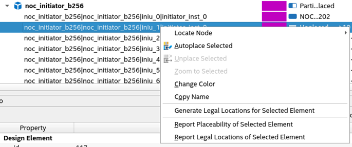
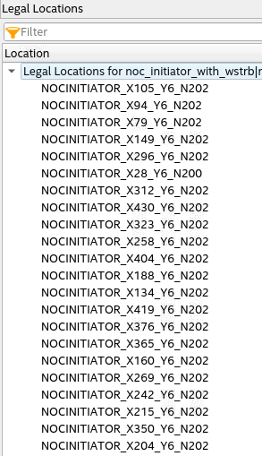
- To assign physical locations to the initiators in your design, right-click an initiator and select Generate Legal Locations for Selected Element. The system displays all legal locations for the selected initiator.
Select the location at which you want to place the initiator. (Refer to Guidelines for Assigning Physical Locations to Initiators, below.)
Guidelines for Assigning Physical Locations to Initiators
For information on the available initiators in the bottom and top hard memory NoC and how they span the sectors relative to the physical UIB location, refer to the NoC User Guide or the NoC techmodule. Note that all HBM targets are placed within the three sectors directly beneath the UIB.
When placing initiators, you should consider the following points:
- The desired initiator–target connectivity.
- The physical arrangement of the targets. (Refer to the table, below.)
Table 47. Target Placements Top UIB - Left UIB - Middle UIB - Right tniu_ch5_u1 tniu_ch7_u1 tniu_ch4_u1 tniu_ch6_u1 tniu_ch5_u0 tniu_ch7_u0 tniu_ch4_u0 tniu_ch6_u0 tniu_ch1_u1 tniu_ch3_u1 tniu_ch0_u1 tniu_ch2_u1 tniu_ch1_u0 tniu_ch3_u0 tniu_ch0_u0 tniu_ch2_u0 Bottom UIB - Left UIB - Middle UIB - Right tniu_ch2_u0 tniu_ch0_u0 tniu_ch3_u0 tniu_ch1_u0 tniu_ch2_u1 tniu_ch0_u1 tniu_ch3_u1 tniu_ch1_u1 tniu_ch6_u0 tniu_ch4_u0 tniu_ch7_u0 tniu_ch5_u0 tniu_ch6_u1 tniu_ch4_u1 tniu_ch7_u1 tniu_ch5_u1 - When choosing physical locations for initiators, follow these recommendations:
- If initiators and targets are to be connected one-to-one, place the initiators closest to the targets.
- For a design containing sixteen initiators, select nine initiators from the three sectors directly beneath the UIB, and three initiators from the sector adjacent to the UIB on the left, and four initiators from the sectors adjacent to UIB on the right. Refer to the figure below for example placement.