4.2.1. General Parameters for High Bandwidth Memory (HBM2E) Interface FPGA IP
The General tab allows you to select HBM2E device configurations, the number of channels that you want to implement, and the controller settings.
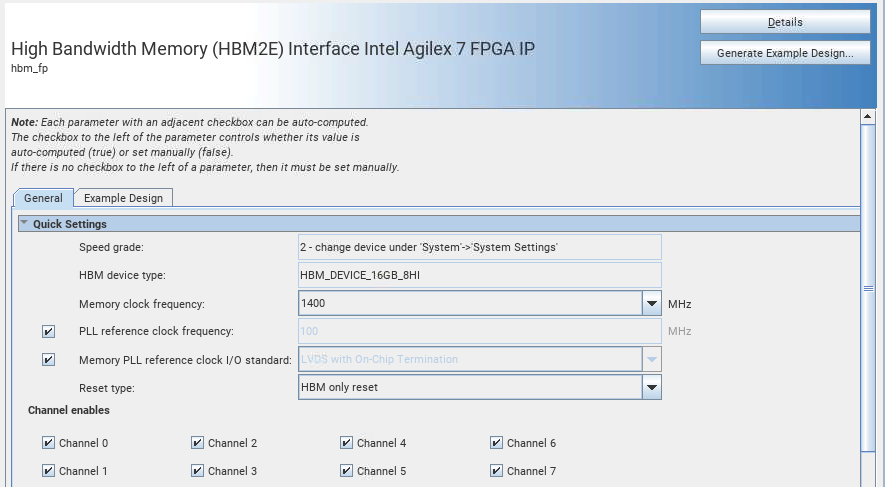
Figure 8. Group: General / Quick Settings
| Display Name | Description |
|---|---|
| Speed Grade | Speed grade of FPGA device and whether it is an engineering sample (ES) or a production device. The value is automatically determined based on the device selected under . If you do not specify a device, the system assumes a production device of the fastest speed grade. You should always specify the correct target device during IP generation; failure to specify the correct device may result in generated IP that does not work on hardware. |
| HBM Device Type | The HBM device type. HBM_DEVICE_16GB_8HI refers to HBM2E device with a total device density of 16GB in a 8-high stack. HBM_DEVICE_8GB_4HI refers to an HBM2E device with a total density of 8GB in a 4-high stack. |
| Memory clock frequency | The frequency of the memory clock in MHz. Specifies the clock frequency for the HBM2E interface. The minimum supported memory clock frequency is 800 MHz and the maximum supported memory clock frequency depends on the FPGA device speed grade.
|
| PLL reference clock frequency | When checked the default value of 100 MHz is used for the PLL reference clock frequency. Uncheck the check box if you want to specify your own PLL reference clock frequency. |
| Memory PLL reference clock I/O standard | Specifies the I/O standard for the PLL reference clock of the memory interface. The only supported termination option is LVDS with on-chip termination. |
| Reset Type | HBM-only reset option resets the entire UIB subsystem, including HBM2E DRAM. When you choose the reset with calibration option, it recalibrates the UIB when you trigger the reset. |
| Channel enables | Select number of channels you want to enable for your HBM2E IP. Each channel selection activates the controllers for the two pseudo-channels of that channel of the UIB block. |
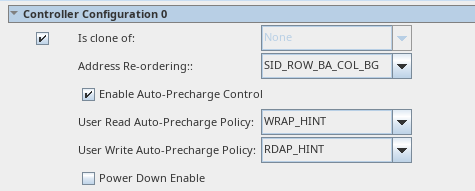
Figure 9. Group: General / Controller Configuration
| Display Name | Description |
|---|---|
| Is clone of | Set this option to make this channel configuration a clone of the selected channel. Parameters are copied from the specified channel. This parameter applies when you enable more than one HBM2E channel. |
| Address Re-ordering | Specifies the pattern for mapping the address from the AXI interface to the HBM2E memory device. By choosing an appropriate address reordering configuration, you help to improve the efficiency of accesses to the HBM2E memory device for the traffic pattern generated by your design. The HBM controller supports three types of address reordering:
Note: The SID-BG-BANK-ROW-COL[5:1] address order limits HBM throughput when memory accesses are sequential, and also affects random access throughput in pseudo-BL8 mode.
|
| Enable Auto-Precharge Control | Select this parameter to enable the auto-precharge control on the controller top level. If you assert the auto-precharge control signal while requesting a read or write burst, you can specify whether the controller should close (precharge) the currently open page at the end of the read or write burst, potentially making a future access to a different page of the same bank faster. |
| User Read Auto-Precharge Policy | Controls the amount of freedom that the controller has when handling auto-precharge requests. FORCED indicates that the controller follows the user auto-precharge request exactly. HINT indicates that the controller may override the auto-precharge request by disabling it when a page hit is detected (that is, if it receives two commands, one with auto-precharge and one without auto-precharge to the same page, the controller changes auto-precharge for the first to 0 so that the second can access the page without reopening it). You can issue the request to precharge together with the read command by asserting aruser[0]. You can choose between two values for this parameter:
|
| User Write Auto-Precharge Policy | Controls the amount of freedom that the controller has when handling auto-precharge requests. FORCED indicates that the controller follows the user auto-precharge request exactly. HINT indicates that the controller may override the auto-precharge request by disabling it when a page hit is detected (that is, if it receives two commands, one with auto-precharge and one without auto-precharge to the same page, the controller changes auto-precharge for the first to 0 so that the second can access the page without reopening it). You can issue a precharge request together with the write by asserting awuser[0]. You can choose between two values for this parameter:
|
| Power Down Enable | Causes the controller to power down when idle. |
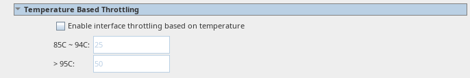
Figure 10. Group: General / Temperature Based Throttling
| Display Name | Description |
|---|---|
| Enable interface throttling based on temperature | Enables temperature-based throttling where the desired throttling ratio can be specified for 2 temperature ranges: 85 to 94 degrees Celsius and 95 to 105 degrees Celsius. The throttling ratio for the 95 to 105 degree range should be greater than or equal to the ratio specified for the 85 to 94 degree range. No throttling is applied below 85 degrees and 100% throttling is applied above 105 degrees. |
| 85C - 94C | This parameter defines the throttle ratio as a percentage (0: no throttling, 100: full throttling) to be applied when the DRAM temperature is between 85 and 94 degrees Celsius. |
| > 95C | This parameter defines the throttle ratio as a percentage (0: no throttling, 100: full throttling) that will be applied when the DRAM temperature is between 95 and 105 degrees Celsius. |
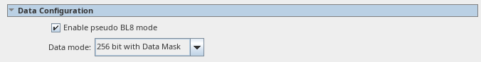
Figure 11. Group: General/Data Configuration
| Display Name | Description |
|---|---|
| Enable pseudo BL8 mode | If enabled, data access granularity is 64B (64 bits per pseudo-channel at BL8) which makes the most efficient use of the NoC and of the controller's command scheduling mechanism. Otherwise data access granularity is 32B (64 bits perpseudo-channel at BL4). The controller uses one or two memory bursts per 64B AXI command, based on this setting. |
| Data mode | Specifies the HBM2E DM pin function and use of HBM ECC data bits.
|
Figure 12. Group: General / Pseudo-Channel n Power Estimation
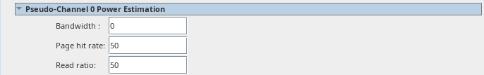
| Display Name | Description |
|---|---|
| Bandwidth | Specify estimated DRAM bandwidth for this pseudo-channel. |
| Page hit rate | Specify estimated DRAM page hit rate for traffic for this pseudo-channel. |
| Read ratio | Specify estimated read ratio for this pseudo-channel. Read ratio is the percentage of DRAM read traffic over write traffic. |