Visible to Intel only — GUID: qze1522111653904
Ixiasoft
2.1. Step 1: Getting Started
2.2. Step 2: Preparing the Base Revision
2.3. Step 3: Preparing the Implementation Revisions for Debug
2.4. Step 4: Tapping Signals in the Implementation Persona
2.5. Step 5: Configuring Data Acquisition
2.6. Step 6: Setting Trigger Conditions
2.7. Step 7: Generating Programming Files
2.8. Step 8: Programming the Board
2.9. Step 9: Performing Data Acquisition
Visible to Intel only — GUID: qze1522111653904
Ixiasoft
2.3. Step 3: Preparing the Implementation Revisions for Debug
In this step you instantiate the SLD JTAG Bridge Host and then add a .stp file to the implementation revisions that you want to debug.
- In the Intel® Quartus® Prime GUI, set blinking_led_slow as the current revision.
- Include sld_host.ip as a project file in the blinking_led_slow implementation revision.
- Uncomment the following blocks of code from blinking_led_slow.sv:
//=================== // Uncomment this block to enable Signal Tap input wire tck, input wire tms, input wire tdi, input wire vir_tdi, input wire ena, output wire tdo, //=================== //=================== // Uncomment this block to enable Signal Tap sld_host u_sld_hostled_two_on ( .tck (tck), // input, width = 1, connect_to_bridge_host.tck .tms (tms), // input, width = 1, .tms .tdi (tdi), // input, width = 1, .tdi .vir_tdi(vir_tdi),// input, width = 1, .vir_tdi .ena (ena), // input, width = 1, .ena .tdo (tdo) // output, width = 1, .tdo ); //=================== - Update the port definition for the PR personas to include the following ports, by uncommenting this block of code in blinking_led_slow.sv and blinking_led_empty.sv files:
module blinking_led_slow ( // clock input wire clock, input wire [31:0] counter, //================= //Uncomment this block to enable Signal Tap input wire tck, input wire tms, input wire tdi, input wire vir_tdi, input wire ena, output wire tdo, //================= // Control signals for the LEDs output wire led_two_on, output wire led_three_on ); - Click Tools > Signal Tap Logic Analyzer to open the Signal Tap Logic Analyzer Window.
Figure 11. Signal Tap Logic Analyzer Window
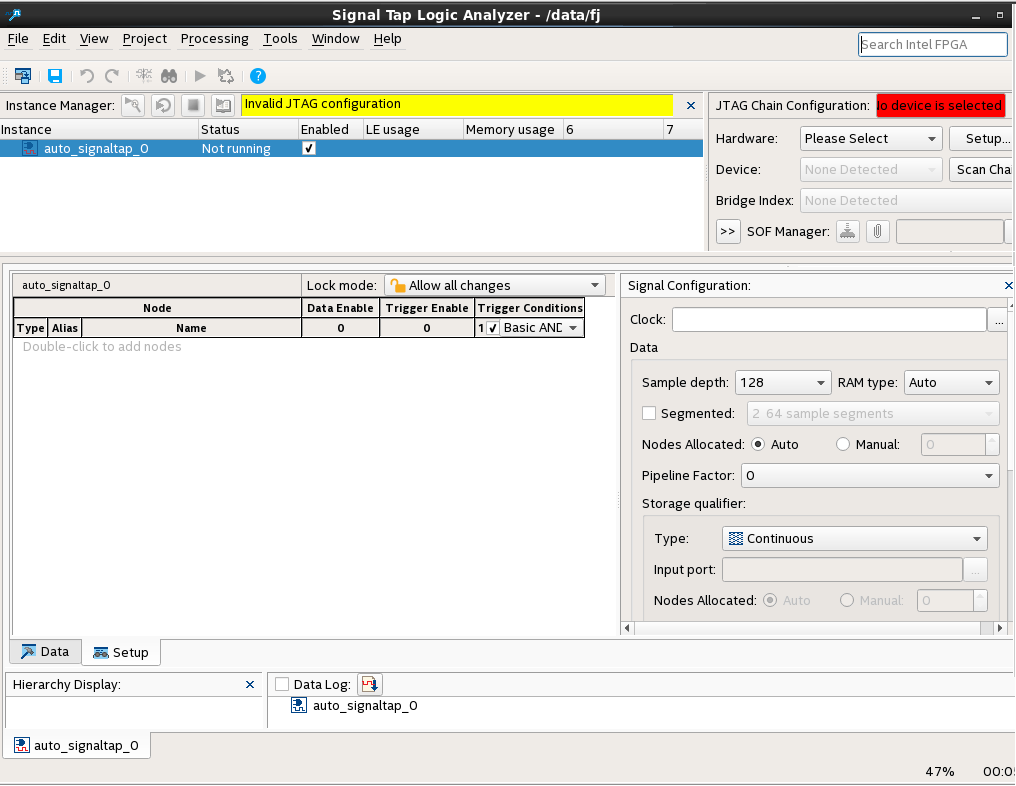
- Click File > Save As..., and save the file as stp_slow.stp.
A dialog box appears prompting you to enable Signal Tap file stp_slow.stp for the current project.Figure 12. Enable stp_slow.stp for the Current Project
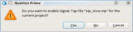
- Click Yes.
Repeat these steps for the blinking_led_default and the blinking_led_empty personas. Use stp_default.stp and stp_empty.stp for the Signal Tap files.
You can disable Signal Tap in the project by clicking Assignments > Settings. In the Category pane select Signal Tap Logic Analyzer. Then, turn off Enable Signal Tap Logic Analyzer.
Related Information