Visible to Intel only — GUID: nik1409855317671
Ixiasoft
1. Transceiver Architecture in Cyclone V Devices
2. Transceiver Clocking in Cyclone V Devices
3. Transceiver Reset Control in Cyclone V Devices
4. Transceiver Protocol Configurations in Cyclone V Devices
5. Transceiver Custom Configurations in Cyclone V Devices
6. Transceiver Loopback Support
7. Dynamic Reconfiguration in Cyclone V Devices
1.3.2.1.1. Word Aligner Options and Behaviors
1.3.2.1.2. Word Aligner in Manual Alignment Mode
1.3.2.1.3. Word Aligner in Bit-Slip Mode
1.3.2.1.4. Word Aligner in Automatic Synchronization State Machine Mode
1.3.2.1.5. Word Aligner in Automatic Synchronization State Machine Mode with a 10-Bit PMA-PCS Interface Configuration
1.3.2.1.6. Word Aligner Operations in Deterministic Latency State Machine Mode
1.3.2.1.7. Programmable Run-Length Violation Detection
1.3.2.1.8. Receiver Polarity Inversion
1.3.2.1.9. Bit Reversal
1.3.2.1.10. Receiver Byte Reversal
3.1. PHY IP Embedded Reset Controller
3.2. User-Coded Reset Controller
3.3. Transceiver Reset Using Avalon Memory Map Registers
3.4. Clock Data Recovery in Manual Lock Mode
Resetting the Transceiver During Dynamic Reconfiguration
3.6. Transceiver Blocks Affected by the Reset and Powerdown Signals
3.7. Transceiver Power-Down
3.8. Document Revision History
3.2.1. User-Coded Reset Controller Signals
3.2.2. Resetting the Transmitter with the User-Coded Reset Controller During Device Power-Up
3.2.3. Resetting the Transmitter with the User-Coded Reset Controller During Device Operation
3.2.4. Resetting the Receiver with the User-Coded Reset Controller During Device Power-Up Configuration
3.2.5. Resetting the Receiver with the User-Coded Reset Controller During Device Operation
4.1.2.1. PIPE Interface
4.1.2.2. Transmitter Electrical Idle Generation
4.1.2.3. Power State Management
4.1.2.4. 8B/10B Encoder Usage for Compliance Pattern Transmission Support
4.1.2.5. Receiver Status
4.1.2.6. Receiver Detection
4.1.2.7. Clock Rate Compensation Up to ±300 ppm
4.1.2.8. PCIe Reverse Parallel Loopback
7.1. Dynamic Reconfiguration Features
7.2. Offset Cancellation
7.3. Transmitter Duty Cycle Distortion Calibration
7.4. PMA Analog Controls Reconfiguration
7.5. Dynamic Reconfiguration of Loopback Modes
7.6. Transceiver PLL Reconfiguration
7.7. Transceiver Channel Reconfiguration
7.8. Transceiver Interface Reconfiguration
7.9. Reduced .mif Reconfiguration
7.10. Unsupported Reconfiguration Modes
7.11. Document Revision History
Visible to Intel only — GUID: nik1409855317671
Ixiasoft
2.2.2.1. Non-Bonded Channel Configurations
This section describes the clock path for non-bonded configurations.
The following table describes the clock path for non-bonded configuration with the CMU PLL and fPLL as TX PLL using various clock lines.
| Clock Line | Transmitter PLL | Clock Path |
|---|---|---|
| x1 | CMU | CMU PLL » x1 » individual clock divider » serializer |
| x6, xN | CMU | CMU PLL » central clock divider » x6 » xN » individual clock divider » serializer 7 |
| fPLL | fPLL » x1_fPLL » central clock divider » x6 » individual clock divider » serializer 7 |
Figure 43. Three Non-Bonded Transmitter Channels Driven by CMU PLL using x1 Clock Line Within a Transceiver Bank
Figure 44. Three Non-Bonded Transmitter Channels Driven by CMU PLL using x6 and xN Clock Lines Across Multiple Transceiver Banks
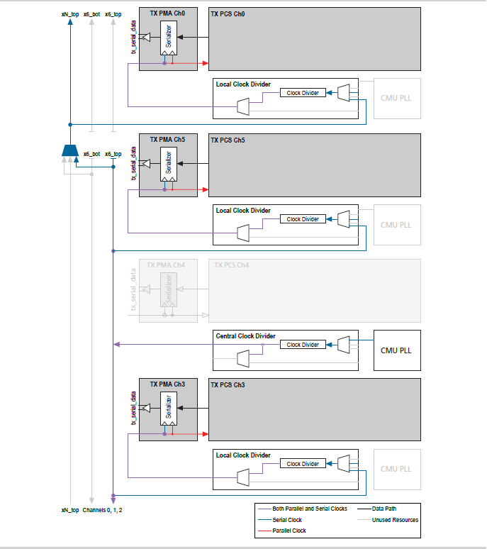
7 Non-bonded channels within the neighboring two banks or within the six channels of TX PLL are driven by clocks from x6 clock line. Channels in other banks outside the six channels are driven by the xN clock line.