Visible to Intel only — GUID: ivj1510161933946
Ixiasoft
1. About the High Bandwidth Memory (HBM2) Interface Intel® FPGA IP
2. Introduction to High Bandwidth Memory
3. Stratix® 10 HBM2 Architecture
4. Creating and Parameterizing the High Bandwidth Memory (HBM2) Interface Intel® FPGA IP
5. Simulating the High Bandwidth Memory (HBM2) Interface Intel® FPGA IP
6. High Bandwidth Memory (HBM2) Interface Intel® FPGA IP Interface
7. High Bandwidth Memory (HBM2) Interface Intel® FPGA IP Controller Performance
8. High Bandwidth Memory (HBM2) Interface Intel® FPGA IP User Guide Archives
9. Document Revision History for High Bandwidth Memory (HBM2) Interface FPGA IP User Guide
4.2.1. General Parameters for High Bandwidth Memory (HBM2) Interface Intel® FPGA IP
4.2.2. FPGA I/O Parameters for High Bandwidth Memory (HBM2) Interface Intel® FPGA IP
4.2.3. Controller Parameters for High Bandwidth Memory (HBM2) Interface Intel® FPGA IP
4.2.4. Diagnostic Parameters for High Bandwidth Memory (HBM2) Interface Intel® FPGA IP
4.2.5. Example Designs Parameters for High Bandwidth Memory (HBM2) Interface Intel® FPGA IP
4.2.6. Register Map IP-XACT Support for HBM2 IP
5.1. High Bandwidth Memory (HBM2) Interface Intel® FPGA IP Example Design
5.2. Simulating High Bandwidth Memory (HBM2) Interface Intel® FPGA IP with ModelSim* and Questa*
5.3. Simulating High Bandwidth Memory (HBM2) Interface Intel® FPGA IP with Synopsys VCS*
5.4. Simulating High Bandwidth Memory (HBM2) Interface Intel® FPGA IP with Riviera-PRO*
5.5. Simulating High Bandwidth Memory (HBM2) Interface Intel® FPGA IP with Cadence Xcelium* Parallel Simulator
5.6. Simulating High Bandwidth Memory (HBM2) Interface Intel® FPGA IP for High Efficiency
5.7. Simulating High Bandwidth Memory (HBM2) Interface IP Instantiated in Your Project
6.1. High Bandwidth Memory (HBM2) Interface Intel® FPGA IP High Level Block Diagram
6.2. High Bandwidth Memory (HBM2) Interface Intel® FPGA IP Controller Interface Signals
6.3. User AXI Interface Timing
6.4. User APB Interface Timing
6.5. User-controlled Accesses to the HBM2 Controller
6.6. Soft AXI Switch
7.1. High Bandwidth Memory (HBM2) DRAM Bandwidth
7.2. High Bandwidth Memory (HBM2) Interface Intel® FPGA IP HBM2 IP Efficiency
7.3. High Bandwidth Memory (HBM2) Interface Intel® FPGA IP Latency
7.4. High Bandwidth Memory (HBM2) Interface Intel® FPGA IP Timing
7.5. High Bandwidth Memory (HBM2) Interface Intel® FPGA IP DRAM Temperature Readout
Visible to Intel only — GUID: ivj1510161933946
Ixiasoft
5.6. Simulating High Bandwidth Memory (HBM2) Interface Intel® FPGA IP for High Efficiency
The default traffic pattern can achieve high efficiency by efficiently utilizing the HBM2 memory bandwidth and providing an efficient flow of traffic between the HBM2 controller and AXI user interface.
The main steps to deriving higher efficiency are:
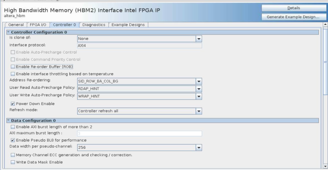
- Turn off Enable Reorder Buffer on the Controller tab. The Reorder Buffer rearranges the read data in the order of the issued requests.
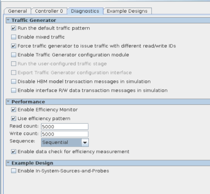
- Turn on Force traffic generator to issue different AXI Read/Write IDs and Enable Efficiency Test Mode on the Diagnostics tab. In this configuration, the traffic generator issues concurrent read and write transactions; consequently, you may receive data mismatch warnings, which you can ignore.
- Turn on Use efficiency pattern and Enable data check for efficiency measurement on the Diagnostics tab, to have the traffic generator use an efficiency pattern to test both synthesis and simulation designs. Ensure that the Read count and Write count values are equal, for the validity check to pass. For best HBM2 efficiency, select a Sequence value of Sequential.
The following sections explain the General, Controller, and Diagnostic tab parameters required to perform high efficiency HBM2 simulation. The following figures illustrate parameter settings for a high-efficiency simulation for a single-channel HBM2 controller.
For more information about improving controller efficiency, refer to High Bandwidth Memory (HBM2) Interface Intel® FPGA IP Controller Performance.
Figure 13. Controller Tab Settings for High Efficiency Simulation


Figure 14. Diagnostics Tab Settings for High Efficiency Simulation

