Visible to Intel only — GUID: tsq1709595612294
Ixiasoft
5.1. GTS Interlaken IP Clock and Reset Interface Signals
5.2. GTS Interlaken IP Transmit User Interface Signals
5.3. GTS Interlaken IP Receive User Interface Signals
5.4. GTS Interlaken IP Management Interface Signals
5.5. GTS Interlaken Link and Miscellaneous Signals
5.6. GTS Interlaken IP Reconfiguration Signals
Visible to Intel only — GUID: tsq1709595612294
Ixiasoft
2.3. Specifying the GTS Interlaken IP Parameters and Options
The IP parameter editor allows you to quickly configure your custom IP variation. You specify IP options and parameters in the Quartus® Prime Pro Edition software.
You must use the IP Catalog accessible from the Quartus® Prime Pro Edition Tools menu.
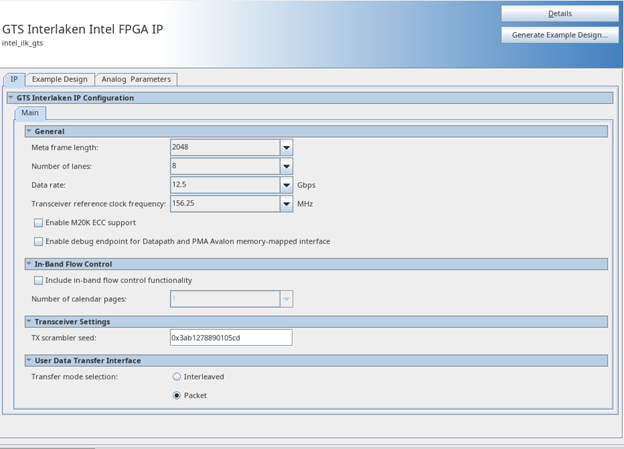
GTS Interlaken IP Parameter Editor


- In the Quartus® Prime Pro Edition software, click File > New Project Wizard to create a new Quartus® Prime project, or File > Open Project to open an existing Quartus® Prime project. The wizard prompts you to specify a device.
- Select the device family Intel Agilex™ 5 (E-Series/D-Series) as your target device.
- In the IP Catalog (Tools > IP Catalog), locate and double-click GTS Interlaken Intel® FPGA IP. The New IP Variant window appears.
- Specify a top-level name for your custom IP variation. The parameter editor saves the IP variation settings in a file named <your_ip> .ip.
- Click Create. The parameter editor appears.
- On the IP tab, specify the parameters and options for your IP variation, including one or more of the following. Refer to Parameter Settings for information about specific IP parameters.
- Specify parameters defining the IP functionality, port configurations, and device-specific features.
- Specify options for processing the IP files in other EDA tools.
- Click Generate HDL. The Generation dialog box appears.
- Specify output file generation options, and then click Generate. The IP variation files generate according to your specifications.
- Select IP-XACT option to create an IP-XACT representation of your generated system.
This selection generates the <ip_name>.ipxact file during the IP generation. The .ipxact file contains generic information about your IP. The IP variant-specific information such as reset and register values may vary across the IP variants.
- Select IP-XACT option to create an IP-XACT representation of your generated system.
- Optionally, click Generate Example Design tab in the parameter editor to generate a demonstration testbench and example design for your IP variation.
- Optionally, click the Analog Parameters tab to set the analog parameters of the F-Tile transceivers. These settings ensure the functionality of the design on hardware.
- Click Finish. The parameter editor adds the top-level .ip file to the project automatically. If you are prompted to manually add the .ip file to the project, click Project > Add/Remove Files in Project to add the file.
- After generating and instantiating your IP variation, make appropriate pin assignments to connect ports.