Visible to Intel only — GUID: ivn1676593200748
Ixiasoft
Visible to Intel only — GUID: ivn1676593200748
Ixiasoft
2.1.1.3.2. Guidelines for Selecting the DDR4 DRAM Component Package Type
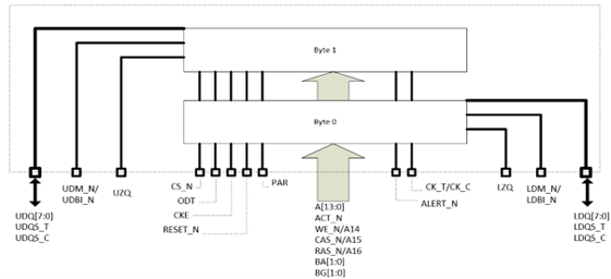
Because the Agilex™ 7 M-Series DDR4 IP does not support x4 discrete memory component/die, you can use only x16 DQ width component for a 2 Dies Per Component, 1 Rank package. In this combination, two x8 dies are combined in a single package to make one x16 component as shown below.

You must set the Device DQ width to 16 when selecting 2 Dies per Component, 1 Rank. Otherwise, the following error message appears: Discrete memory device consists of x4 die is not supported by the current version of Platform Designer.
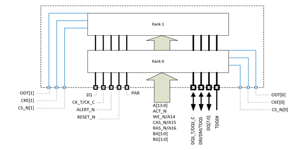
For a 2 Dies Per Component, 2 Rank package, the DQ Width of the component is the same as the base die; it is essentially two ranks of the base die, as illustrated below.

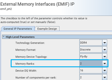
You must set the Memory Ranks to 2 when parameterizing an EMIF IP using a custom preset file generated with a 2 Dies per Component, 2 Rank package. Otherwise, the following error message appears: The number of ranks in each memory component (2) cannot divide the total number of ranks in the interface (1).
