Visible to Intel only — GUID: azl1475769383630
Ixiasoft
2.1. Stratix® 10 DisplayPort SST Parallel Loopback Design Features
2.2. Stratix® 10 DisplayPort SST TX-only or RX-only Design Features
2.3. Design Components
2.4. Clocking Scheme
2.5. Interface Signals and Parameters
2.6. Hardware Setup
2.7. Simulation Testbench
2.8. DisplayPort Transceiver Reconfiguration Flow
2.9. Transceiver Lane Configurations
Visible to Intel only — GUID: azl1475769383630
Ixiasoft
2.7. Simulation Testbench
The simulation testbench simulates the DisplayPort TX serial loopback to RX.
Note: The DisplayPort 2.0 simulation testbench is not supported in the current release.
Figure 10. DisplayPort Intel® FPGA IP Simplex Mode Simulation Testbench Block Diagram
| Component | Description |
|---|---|
| Video Pattern Generator | This generator produces color bar patterns that you can configure. You can parameterize the video format timing. |
| Testbench Control | This block controls the test sequence of the simulation and generates the necessary stimulus signals to the TX core. The testbench control block also reads the CRC value from both source and sink to make comparisons. |
| RX Link Speed Clock Frequency Checker | This checker verifies if the RX transceiver recovered clock frequency matches the desired data rate. |
| TX Link Speed Clock Frequency Checker | This checker verifies if the TX transceiver recovered clock frequency matches the desired data rate. |
The simulation testbench does the following verifications:
| Test Criteria | Verification |
|---|---|
|
Integrates Frequency Checker to measure the Link Speed clock's frequency output from the TX and RX transceiver. |
|
|
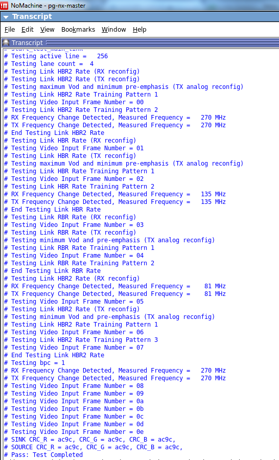
A successful simulation ends with the following message:


| Simulator | Supported Platform | Supported Language |
|---|---|---|
| Riviera-PRO* | Windows/Linux | VHDL and Verilog HDL |
| QuestaSim* | Windows/Linux | VHDL and Verilog HDL |
| Xcelium* Parallel | Linux | Verilog HDL |
| VCS* / VCS* MX | Linux | VHDL and Verilog HDL |